Fuel cell system

a fuel cell and system technology, applied in the direction of fuel cells, solid electrolyte fuel cells, electrical equipment, etc., can solve the problems of interfering with oxygen supply and inhibiting power-generation reaction, and achieve the effect of accurate finding

Active Publication Date: 2012-01-10
TOYOTA JIDOSHA KK
View PDF8 Cites 6 Cited by
  • Summary
  • Abstract
  • Description
  • Claims
  • Application Information

AI Technical Summary

Benefits of technology

The present invention provides a fuel cell system with an accurate way to detect if there are any blockages in its gas flow paths. This helps it determine when to turn on/off heating elements for better energy efficiency.

Problems solved by technology

This patent describes a problem where a fuel cell used for generating electricity can stop operating due to its decrease in temperature caused by cooling down from low temperatures after startup. When the fuel cell starts up again, it may also get frozen because there is no enough hydrogen available for combustion. To solve these issues, a warm-up process is conducted before restarting the fuel cell.

Method used


Image

  • Fuel cell system
  • Fuel cell system
  • Fuel cell system

Examples


Embodiment Construction

[0023]Embodiments of the invention will be described below with reference to the attached drawings. In order that the description can easily be understood, the same components are given the same reference numerals to the extent possible in the respective drawings, and any repetitive description will be omitted.

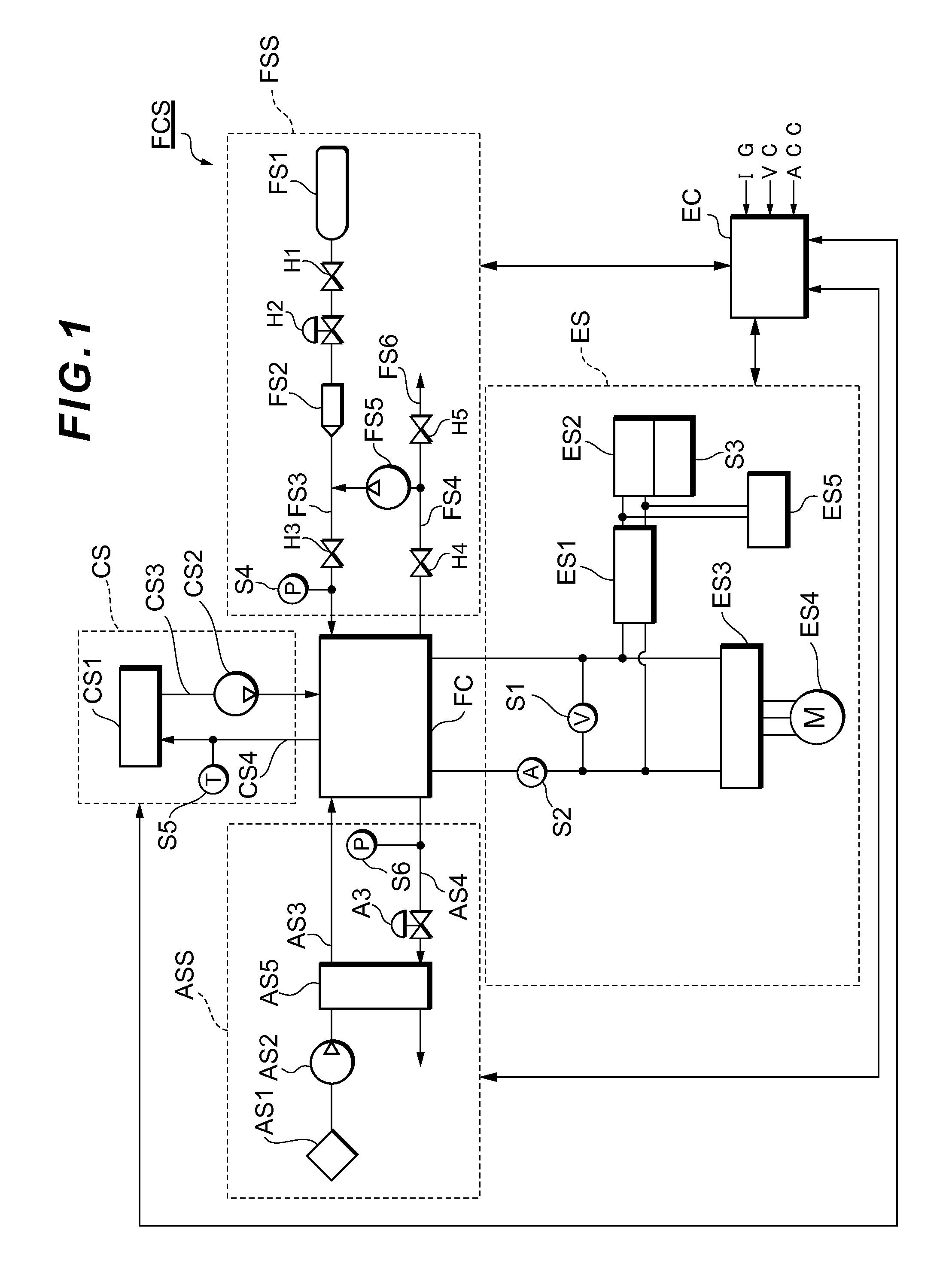
[0024]First, a fuel cell system FCS to be installed in a fuel cell vehicle according to an embodiment of the invention will be described with reference to FIG. 1. FIG. 1 is a diagram showing the system configuration of a fuel cell system FCS that functions as an on-vehicle power source system of a fuel cell vehicle. The fuel cell system FCS can be installed in vehicles such as fuel cell cars (FCHV), electric cars or hybrid cars.

[0025]The fuel cell system FCS has: a fuel cell FC; an oxidant gas supply system ASS; a fuel gas supply system FSS (anode circulation system); an electric power system ES; a cooling system CS; and a controller EC. The fuel cell FC receives the supply of re


PUM


Abstract

Provided is a fuel cell system that performs a warm-up operation by reducing a supply of oxidant gas to a fuel cell, the system having: a fuel cell; and a control unit that regulates amounts of oxidant gas and fuel gas supplied to the fuel cell and controls a power-generation state of the fuel cell. During the warm-up operation with a reduced supply of oxidant gas to the fuel cell, the control unit varies a voltage of the fuel cell for a short period of time to obtain current-voltage characteristics which indicate a relationship of an output voltage and an output current of the fuel cell, calculates an effective catalyst area of the fuel cell based on the obtained current-voltage characteristics, and determines whether the warm-up operation of the fuel cell can be stopped or not based on the calculated effective catalyst area.

Description


Claims


Application Information

Patent Timeline
Owner TOYOTA JIDOSHA KK
Why Eureka
Try Eureka