MOS pipe interface state testing method

A technology of MOS tube and testing method, which is applied in the field of testing the interface state in MOS tube, can solve problems such as time-consuming and complicated process, and achieve the effect of rapid judgment basis

Inactive Publication Date: 2008-03-05
SHANGHAI INTEGRATED CIRCUIT RES & DEV CENT
View PDF0 Cites 25 Cited by
  • Summary
  • Abstract
  • Description
  • Claims
  • Application Information

AI Technical Summary

Problems solved by technology

Because the traditional charge pump method requires a very complicated calculation process, it is necessary to measure a series of charge pump curves under different bias voltages by continuously changing the bias voltage of the drain terminal and the substrate, and calculate the Only by capturing the effective channel length of the interface state, and then deriving the effective channel length can the interface state density at different positions be calculated. Therefore, when the traditional charge pump test method extracts the interface states at different positions of the device, a large number of tests and tests are required. Calculations are complex and time consuming

Method used


Image

  • MOS pipe interface state testing method
  • MOS pipe interface state testing method
  • MOS pipe interface state testing method

Examples


Example Embodiment

[0027] The method for testing the interface state of the MOS tube of the present invention will be described in further detail below with reference to the accompanying drawings.

[0028] In this embodiment, the test object MOS tube is a 14V high-voltage MOS tube device. After 100s of hot carrier injection, the interface state test is performed on it.

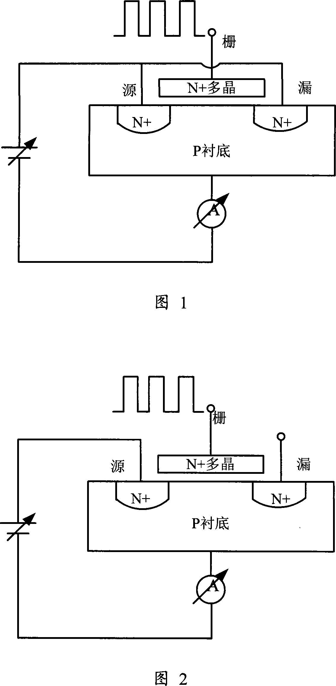
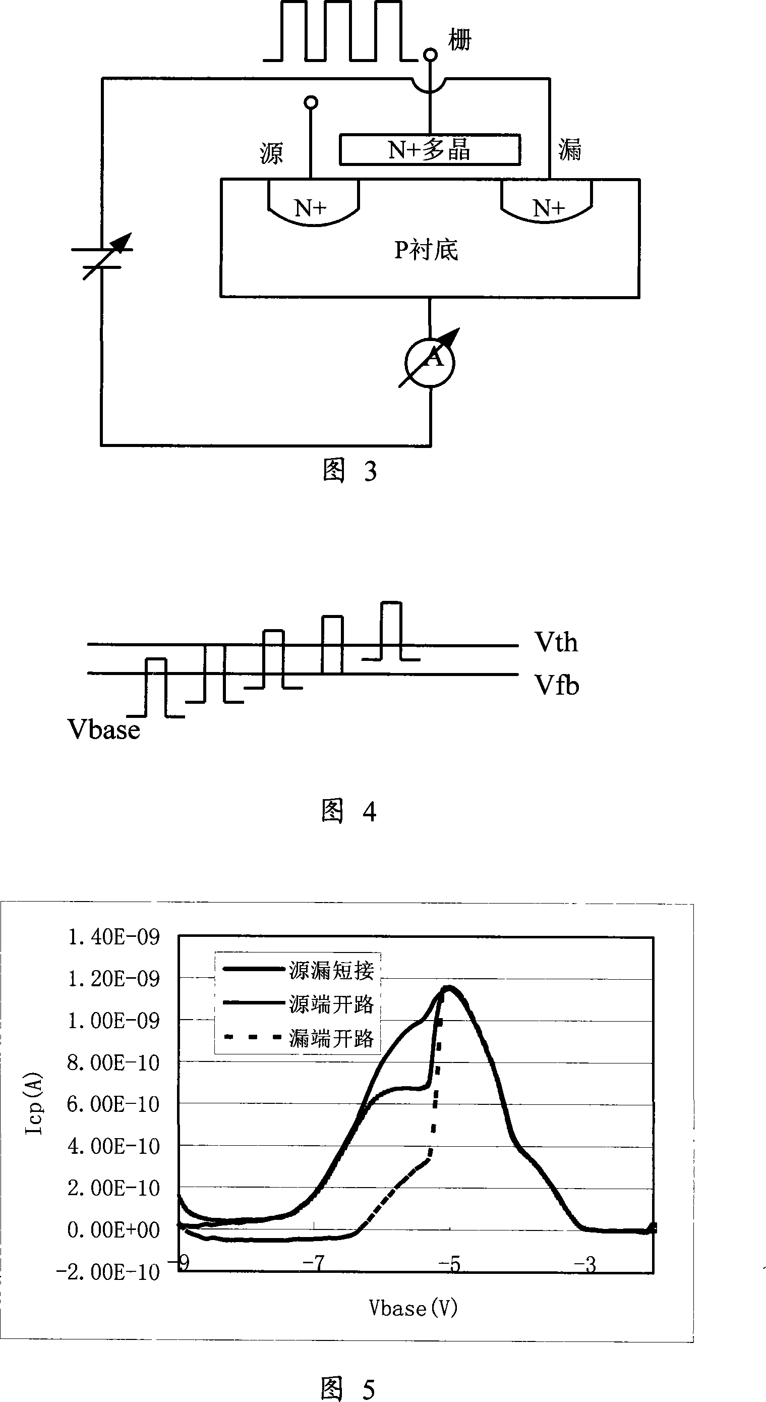
[0029] As shown in Figure 1, using the standard charge pump test method, short-circuit the source and drain of the MOS tube to the substrate electrode, and insert a voltage that reverse biases the source substrate. Add a fixed frequency and fixed amplitude pulse voltage as shown in Figure 4 to the grid. The amplitude of the pulse voltage is greater than the threshold voltage V th Flat belt voltage V fb Differential pressure, reference voltage V base Scan from -10V to 0V, so that the voltage amplitude gradually crosses the threshold voltage V th Flat belt voltage V fb . In this way, an I can be measured cp -V base curve.

[0030] The dr


PUM


Abstract

This invention provides a test method for interface state of MOS transistors including: 1, applying a test method of charge pump to test a current curve of the charge pump and getting current curves of another two pumps by opens of a leakage and a source, 2, separating same and different parts of the three curves to get current of the pump at the source, leakage and channel, 3, obtaining densities of the three places by the current of the charge pump at the source, leakage and the channel.

Description


Claims


Application Information

Patent Timeline
Owner SHANGHAI INTEGRATED CIRCUIT RES & DEV CENT
Why Eureka
Try Eureka