Improved microwave sulfur lamp

A sulfur lamp and microwave technology, which is applied in the field of lighting equipment, can solve the problems of affecting the use effect of microwave sulfur lamps, damaging the magnetron, and long lighting time, so as to improve the problem of one-time lighting failure, improve work performance and use effect ideal effect

Inactive Publication Date: 2008-05-28
LG ELECTRONICS (TIANJIN) APPLIANCES CO LTD
View PDF0 Cites 1 Cited by
  • Summary
  • Abstract
  • Description
  • Claims
  • Application Information

AI Technical Summary

Benefits of technology

This new type of microwaves Sulfur lamps has several technical benefits: they have an internal surface filled with fluorescing material called mercury vapor (Hg) inside them; this process helps convert electrical signals into visible rays for better visibility during low-light conditions compared to traditional lights used indoor environments such as incandesence tubular lanterns. Additionally, these lamps are designed without any moving parts like motors, making their operation faster than previous designs while also improving its overall efficiency over existing systems.

Problems solved by technology

This patented describes different types of microsulfide lamps (MSL). These include traditional microstrobe lamps like sodium nitride flashlamp), LED lights, LCD displays, lasers, and others. However these new type lamps require higher power compared to previous models due to their longer lifespan and better optical properties for specific applications where bright white light can replace incandescents. Additionally, they may use harmful chemical gases instead of electrically generated fluorescers, making them safer and environment friendly overall.

Method used


Image

  • Improved microwave sulfur lamp
  • Improved microwave sulfur lamp
  • Improved microwave sulfur lamp

Examples


preparation example Construction

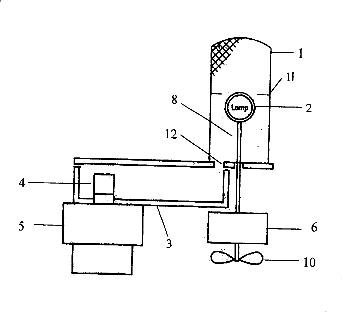
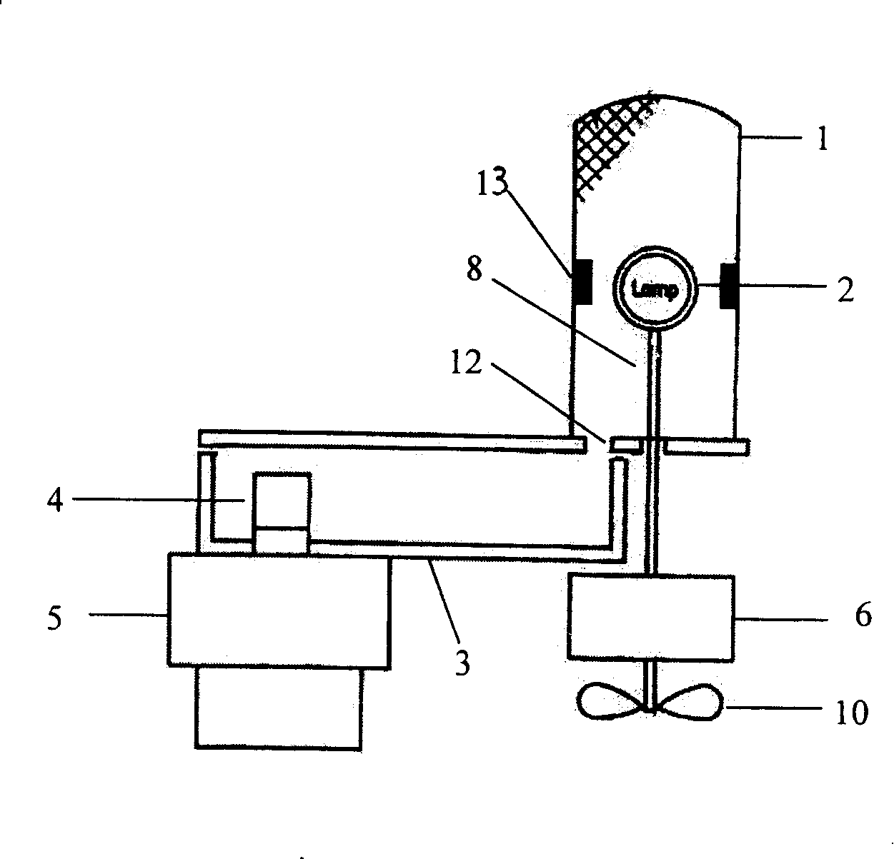
[0026] The preparation method of the microwave sulfur lamp in the embodiment of the present invention is the same as the preparation method of the existing microwave sulfur lamp, so it will not be repeated here. The improvement is that there are two corresponding antenna feed structures on the inner wall of the resonant cavity. The antenna feed structure uses a shaping die to stamp the aluminum into a needle-shaped body with a radius of 1mm and a length of 1mm, and then Welding is fixed on the inner wall of the resonant cavity corresponding to the horizontal position of the center of the bulb.

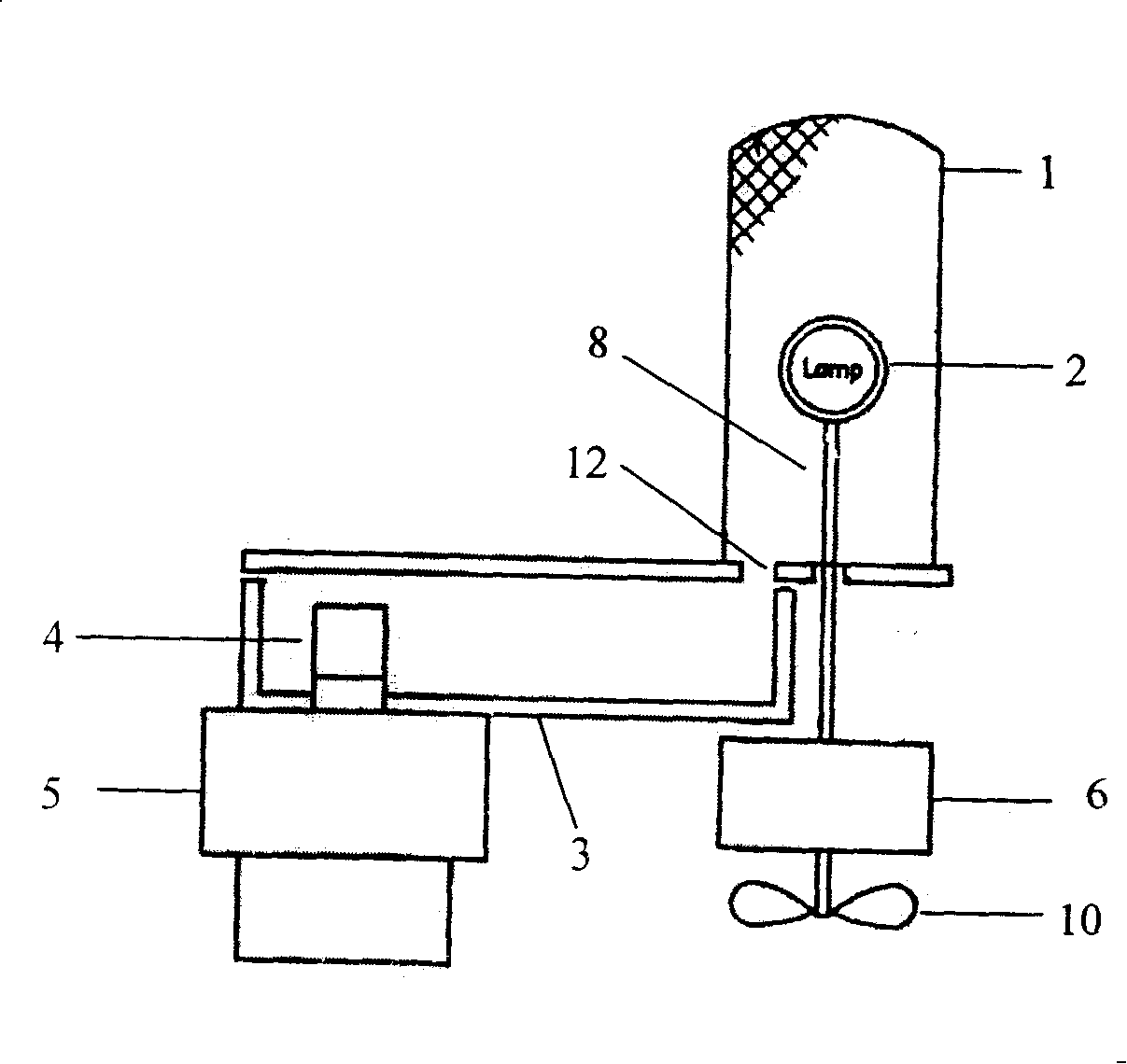
[0027] When the improved microwave sulfur lamp of the present invention works, its work process is identical with the work process of existing microwave sulfur lamp (as figure 1 As shown), when the power is turned on, the bulb 2 set in the resonant cavity 1 is driven by the motor 6 through the lamp handle 8 to rotate, and the microwave energy emitted by the magnetron 5 is transmitted by t


PUM

PropertyMeasurementUnit
Radiusaaaaaaaaaa
Lengthaaaaaaaaaa

Abstract

The invention relates to an improved microwave sulfur lamp, which comprises a lamp bulb, a lamp handle, a resonant cavity, a magnetron, a waveguide cavity, a motor, a coupling window and a fan. The inner wall of the resonant cavity is provided with two corresponding antenna reclaiming energy structures, and the antenna reclaiming energy structures are in shape of a needle, which causes the microwave energy transferred to the resonant cavity to be more centralized at a central position of the lamp bulb and luminescent substances in the bulb shell of the lamp tube to form the molecular energy level transition under the excitation of higher microwave energy to generate the continuous spectrum; or two corresponding electrodes are arranged on the inner wall of the resonant cavity, and the corresponding electrodes are slices which are in shape of geometry, which causes the central position of the lamp bulb to form the electric field to enhance and stimulate in an assistant way the energy of the luminescent substances in the bulb shell of the lamp tube, thus, the illumination time of the bulb can be shortened, and the problem of one time illumination failure is improved.

Description


Claims


Application Information

Patent Timeline
Owner LG ELECTRONICS (TIANJIN) APPLIANCES CO LTD
Why Eureka
Try Eureka