Device for producing copper anode plate and method thereof

A copper anode plate and spray device technology, applied in pig iron foundry, process efficiency improvement, photography process and other directions, can solve the problems of high labor intensity, large investment, inconvenient production, etc., and achieve simple installation and labor. Low strength, small footprint effect

Inactive Publication Date: 2008-10-01
安徽富华电子集团有限公司
View PDF0 Cites 4 Cited by
  • Summary
  • Abstract
  • Description
  • Claims
  • Application Information

AI Technical Summary

Problems solved by technology

[0002] The traditional equipment for producing copper anode plates is mostly of the turntable type, which not only requires a large investment, but also the process is very complicated, the production is also inconvenient, the labor intensity is relatively high, and there is no guarantee for the personal safety of the operators. Economic value and social value considerations cannot be guaranteed

Method used


Image

  • Device for producing copper anode plate and method thereof

Examples


Example Embodiment

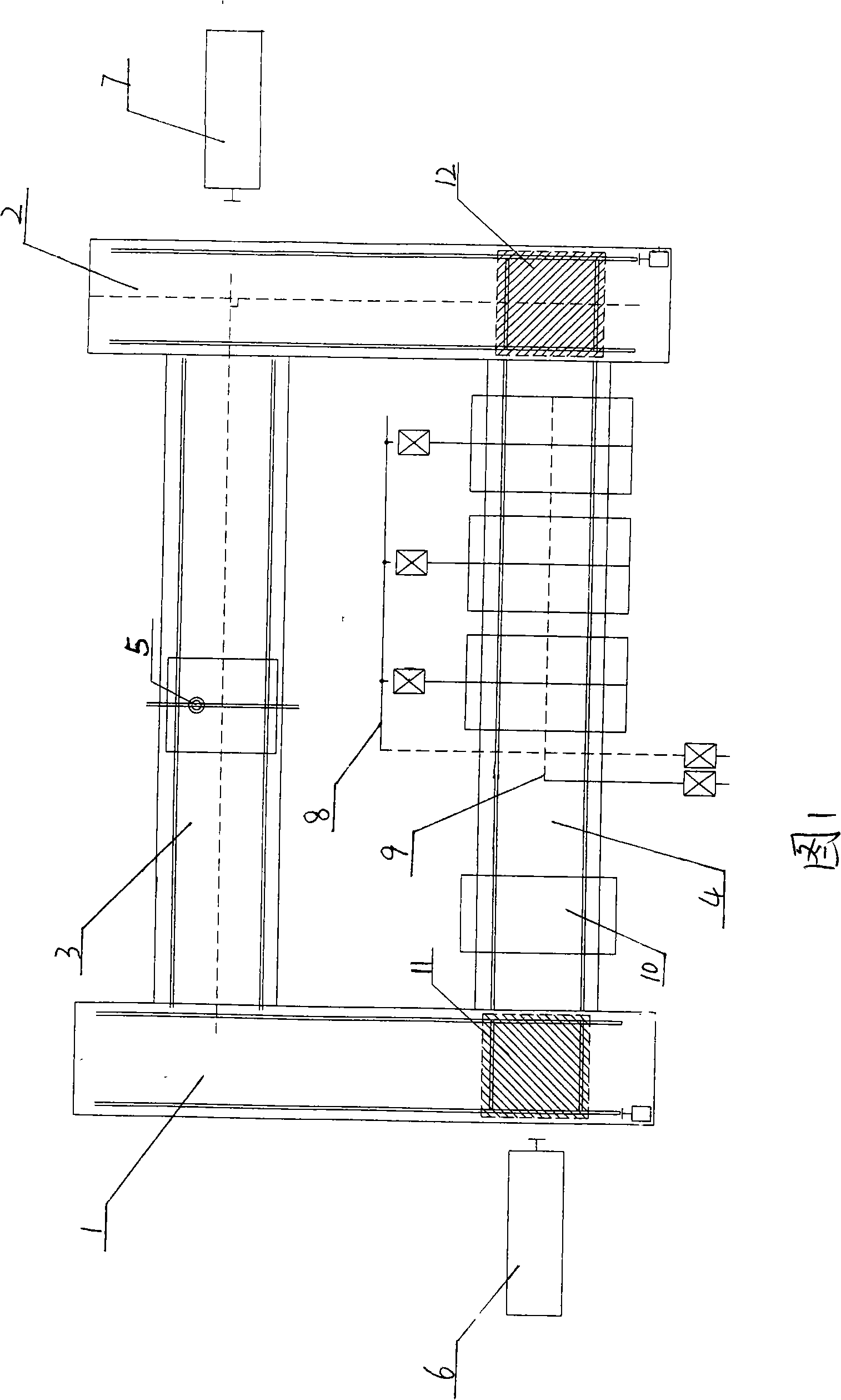
[0020] The present invention will be further described below in conjunction with the accompanying drawings.

[0021] Two parallel longitudinal rails 1 and 2 are arranged, and two front and rear transverse rails 3 and 4 are arranged between the two longitudinal rails 1 and 2. The height of the longitudinal rails 1 and 2 is lower than the transverse rails 3 and 4. Movable trailers 11 and 12 are arranged on the rails 1 and 2, and a carriage is installed on the trailer, and the carriage is provided with a joint track which is in the same direction as the transverse rail and is flush with it; The right side of a transverse track 3 is respectively provided with a push cylinder 6,7. Copper water pouring ladles 10 and cold water spraying devices 8 are installed sequentially from left to right on the top of the latter horizontal track 4, and a spraying device 9 for spraying water upwards is installed below, and pouring templates are sequentially arranged on the latter horizontal track 4,


PUM


Abstract

The invention discloses a device and a method for producing a copper anode plate, and is characterized in that the device comprises two parallel and longitudinal railways, two front and back transverse railways are arranged between the two longitudinal railways, the height of the longitudinal railways is lower than that of the transverse railways, a movable trailer is arranged on the longitudinal railways, a trailing bar is arranged on the trailer, a joint railway that is in the same direction and in parallel and level with the transverse railways is arranged on the trailing bar, and two pushing air cylinders are respectively arranged at the left of the back transverse railway and at the right of the front transverse railway. The device for producing the copper anode plate has the advantages that the device occupies little land area, has simple fundamental installation, saves time and materials, does not need other mechanical power, and is safer relatively to human bodies and has quicker cooling and low laboring intensity.

Description


Claims


Application Information

Patent Timeline
Owner 安徽富华电子集团有限公司
Why Eureka
Try Eureka