Light-emitting diode (LED) and method for preparing LED and base of LED

A technology of light-emitting diodes and a manufacturing method, which is applied in the fields of semiconductor/solid-state device manufacturing, electrical components, electric solid-state devices, etc., can solve the problem that Kina diodes are easy to generate holes, damage the reliability of light-emitting diodes, and the Kina diodes cannot be small. issues such as

Active Publication Date: 2009-09-02
BRIGHT LED ELECTRONICS CORP
View PDF0 Cites 4 Cited by
  • Summary
  • Abstract
  • Description
  • Claims
  • Application Information

AI Technical Summary

Benefits of technology

This technology helps prevent damage from external factors such as sunlight or other sources during manufacturing processes used to create semiconductor devices like transistors on silicone substrates. By applying this coatings over these components without exposure them, they are protected against environmental influences while still allowing their function properly.

Problems solved by technology

This patented describes different types of LED devices used for displaying images or lights. These include small sizes but they still have issues like causing damage caused by static electricity during use due to their dimensions. To solve these problem, there was developed a new type called LCZERG where certain parts were added between adjacent ones of the crystals instead of just placing them together. By filling up any space around the cryds without covering anything outside, the device becomes more reliable even if its dimension decreases downward towards zero volts.

Method used


Image

  • Light-emitting diode (LED) and method for preparing LED and base of LED
  • Light-emitting diode (LED) and method for preparing LED and base of LED
  • Light-emitting diode (LED) and method for preparing LED and base of LED

Examples


Embodiment Construction

[0030] The present invention will be described in detail below in conjunction with the accompanying drawings and embodiments.

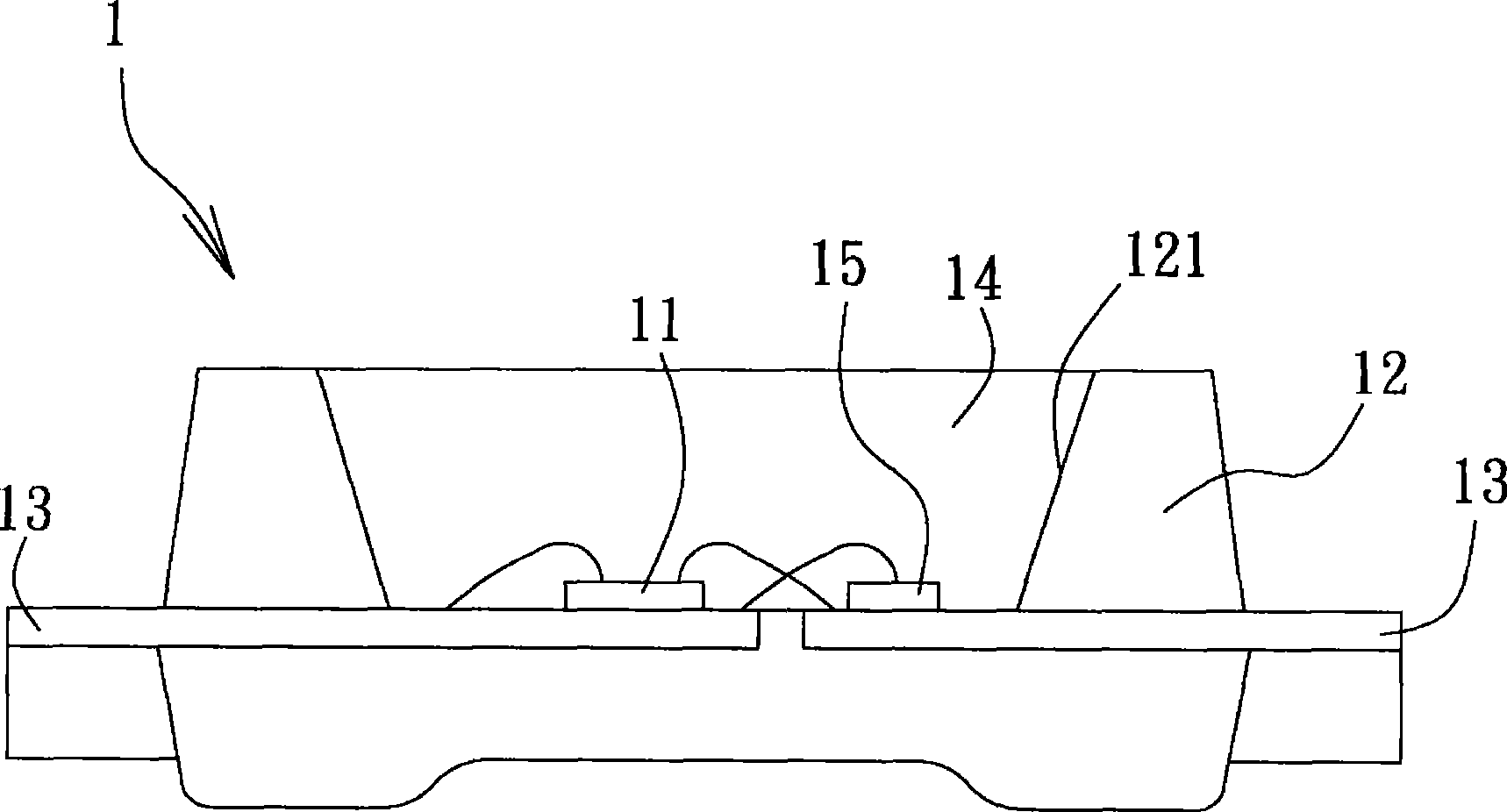
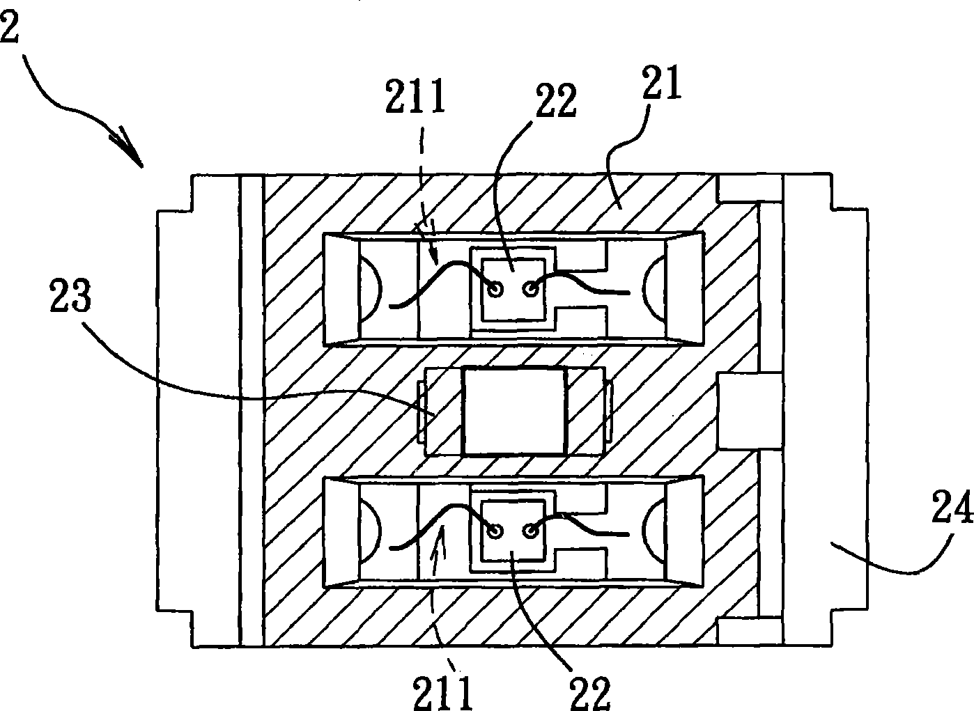
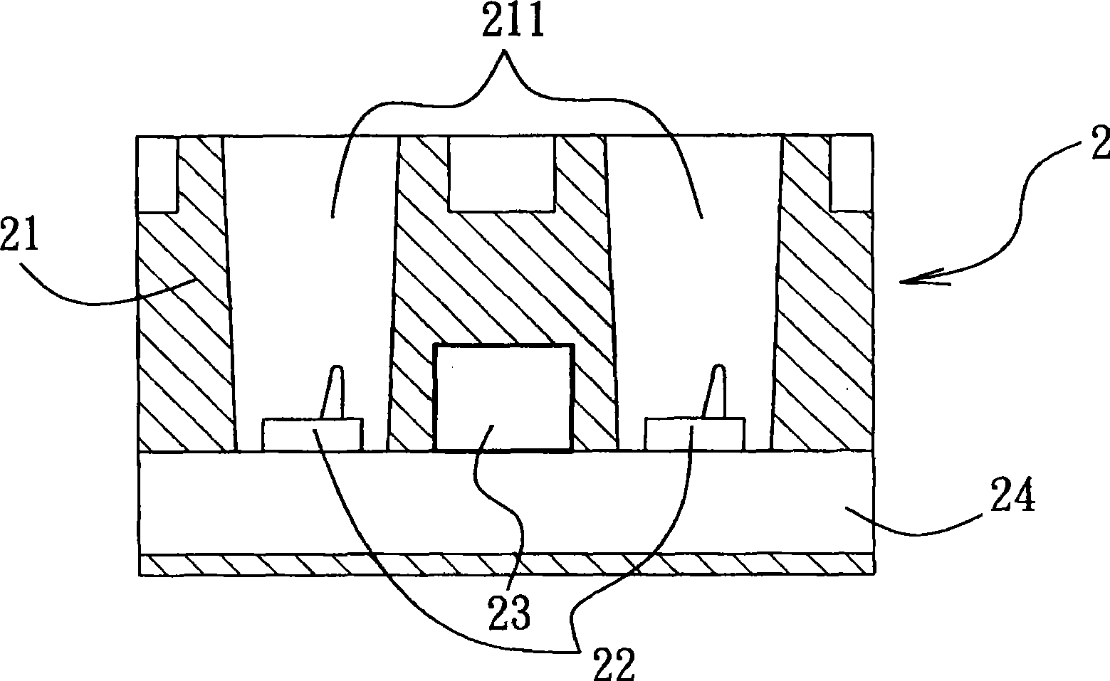
[0031] refer to Figure 4 and Figure 5 , The first preferred embodiment of the light emitting diode 3 and its manufacturing method of the present invention includes a base 4 , a crystal grain 5 and a transparent colloid 6 . The base 4 includes a plastic base 41 , a metal bracket 42 , a Zener diode 43 , a wire 44 and a covering glue 45 .

[0032] The plastic base 41 has a bottom wall 412 and a ring wall 413 defining a groove 411. The material is opaque and highly reflective. In this embodiment, the plastic base 41 is made of white thermoset type resin (by injection molding or compression molding). The metal bracket 42 has two legs 421, 422 spaced apart from each other, accommodated in the plastic base 41 and partly exposed from the plastic base 41, one end of each of the legs 421, 422 is exposed on the bottom wall 412, and the other end extends horizo


PUM


Abstract

The invention provides a light-emitting diode (LED), and a method for preparing the LED and a base of the LED, in particular to an LED. The LED comprises two spacing supporting legs, a Zener diode, a coating colloid and a plastic base. The Zener diode is arranged on one supporting leg, electrically connected with the supporting leg and electrically connected with the other supporting leg by a conductor wire. The coating colloid covers and completely shields the Zener diode and the conductor wire; furthermore, the plastic base accommodates and completely shields the coating colloid so that the grains can be arranged at the very center of the groove of the base, thus avoiding the Zener diode absorbing the light beam emitted by the grains. The coating colloid can protect the Zener diode before the plastic base is formed; furthermore, as the surface is a smooth arc, the plastic base can be attached to the coating colloid closely and is not easy to generate cavities when being formed.

Description


Claims


Application Information

Patent Timeline
Owner BRIGHT LED ELECTRONICS CORP
Why Eureka
Try Eureka