Conveying device

A technology of conveying equipment and vehicle frame, which is applied in the field of mechanized conveying equipment in the assembly line of automobile assembly workshops. It can solve the problems of unsuccessful transfer, lower production efficiency, and poor commonality, so as to reduce production costs and improve production efficiency. Effect

Active Publication Date: 2010-05-05
CHERY AUTOMOBILE CO LTD
View PDF6 Cites 14 Cited by
  • Summary
  • Abstract
  • Description
  • Claims
  • Application Information

AI Technical Summary

Benefits of technology

The guiding rails described by this patented technology have three types: circular or ring-shaped ones with openings between them for easy movement during use. This design helps improve productivity while reducing costs compared to traditional methods like linear motion systems.

Problems solved by technology

This patented describes how current methods involve transporting parts from one part to another during manufacturing operations that can be complex due to the addition or replacement of conveyor devices needed when changing products. Additionally, there are limitations associated with older systems where they were designed without considering future changes required by new designs.

Method used


Image

  • Conveying device
  • Conveying device
  • Conveying device

Examples


Embodiment Construction

[0020] The present invention will be further described below in conjunction with accompanying drawing:

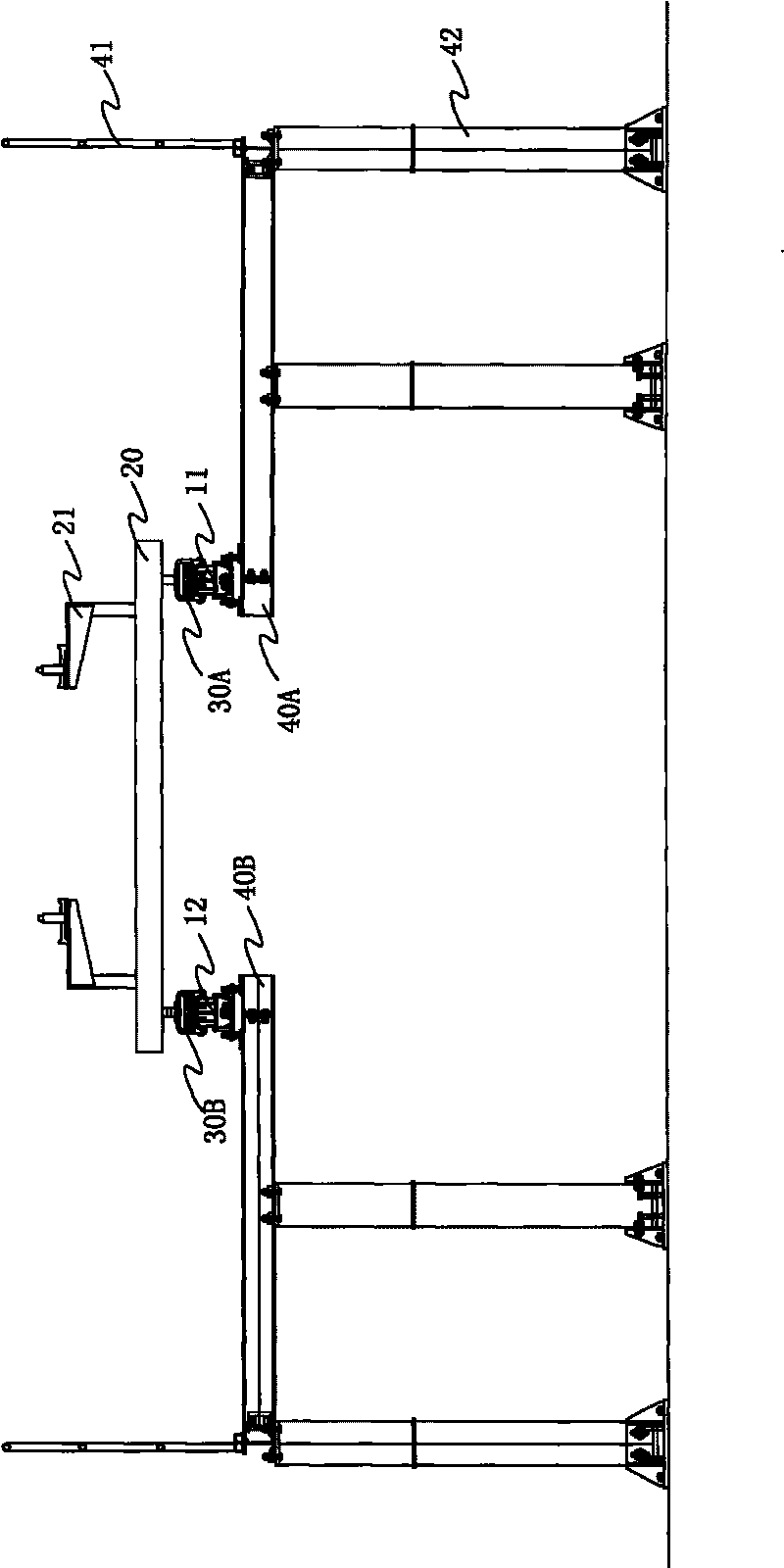
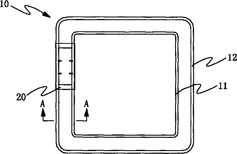
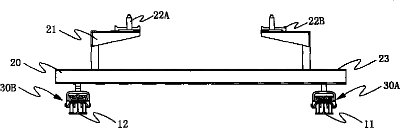
[0021] Such as figure 1 , figure 2 , image 3 The conveying equipment shown includes a guide rail 10 and a vehicle frame 20. The vehicle frame 20 is provided with a traveling mechanism to form a rolling fit with the guide rail 10. The vehicle frame 20 is powered by a driving device to walk in the direction defined by the guide rail 10. The guide rail 10 consists of two mutually parallel and closed orbits.

[0022] The guide rail 10 is ring-shaped, including inner and outer rails 11, 12, the straight sections of the inner and outer rails 11, 12 are parallel to each other, there are circular arc segments at the four corners for smooth transition and the circular arc segments are concentric arcs, and the inner and outer rails 11, 12 are parallel to each other. The rails 11 and 12 are respectively surrounded by two H-shaped steels with the same cross-section in a way that thei


PUM


Abstract

The invention relates to a conveying device, in particular to a conveying device for the flow line production mechanization in an automobile general assembly shop. The conveying device comprises a guide rail and an automotive chassis, a running mechanism is arranged on the automotive chassis and forms rolling cooperation with the guide rail, the automotive chassis moves along the limit direction of the guide rail under the driving of a driving device, and the guide rail is composed of two parallel closed rails. In the technical proposal, the guide rail in the invention is composed of two parallel closed rails, namely a circular rail, by utilizing the rolling cooperation of the running mechanism on the automotive chassis and the guide rail, the automotive chassis can move along the guide rail, therefore, all the working procedures are finished on the guide rail, thereby realizing the streamline operation, the production efficiency is increased and the production cost is reduced simultaneously.

Description


Claims


Application Information

Patent Timeline
Owner CHERY AUTOMOBILE CO LTD
Why Eureka
Try Eureka