Composite flow valve

A circulation valve and composite material technology, applied in sliding valves, valve details, control valves, etc., can solve the problems of high pressure, cost reduction, and low cost, and achieve the effects of no harm to health, cost reduction, and no harm to environmental protection

Inactive Publication Date: 2010-06-16
重庆启蓝科技有限公司
View PDF0 Cites 0 Cited by
  • Summary
  • Abstract
  • Description
  • Claims
  • Application Information

AI Technical Summary

Benefits of technology

This patented technology allows for better control over fluid flows by utilizing a special material called a composite valve with specific properties such as high strength at elevated temperatures while reducing cost compared to traditional materials like metal or plastic.

Problems solved by technology

This patented technical problem addressed by this patents relates to finding ways for reducing or eliminating certain substances from fluids being tested without compromising their safety during testing procedures.

Method used


Image

  • Composite flow valve
  • Composite flow valve
  • Composite flow valve

Examples


Embodiment Construction

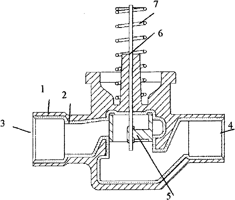
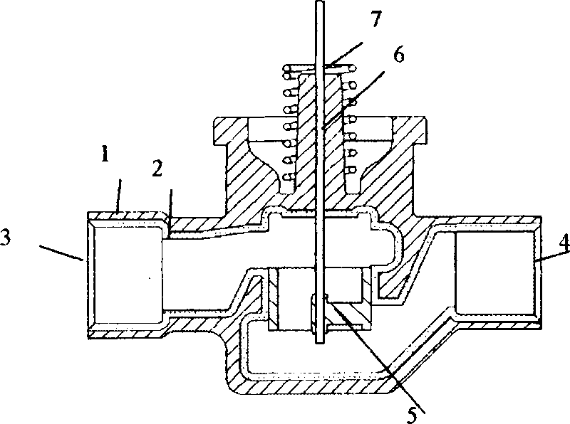
[0010] exist figure 1 , figure 2 Among them, the composite flow valve includes a valve base, a valve core (5), a valve core guide rod (6), a pressure spring (7), a valve inlet (3) of a fluid inlet, and a valve outlet (4) of a flow outlet. The valve base is composed of an outer valve base shell (1) and an inner liner (2), the inner surface of the outer valve base shell (1) is put into the inner liner (2), and the two are closely combined to form a composite material. Again figure 1 , figure 2 In the composite flow valve as a one-way valve, when the fluid pressure at the valve inlet (3) is greater than the fluid pressure at the valve outlet (4), the valve core (5) opens along the valve core guide rod (6), and the fluid passes through. When the fluid pressure at the valve outlet (4) is greater than the valve inlet (3), the valve core (5) closes along the valve core guide rod (6), and the inner liner (2) with a certain thickness acts as the contact surface of the fluid, which ca


PUM


Abstract

The invention discloses a composite flow valve with a composite material valve base, which comprises the valve base, a valve core, a valve core guide rod, a pressure springs, a fluid intake valve inlet and a flow discharge valve outlet, wherein the valve base consists of an external valve base shell and an internal liner body; the inside surface of the external valve base shell is lined with the internal liner body, and the external valve base shell and the internal liner body are tightly combined to form a composite material. The internal liner body with a certain thickness has a fluid contact surface; and the internal liner body of the valve base can be made of corresponding materials according to different use requirements on the composite flow valve. The external valve base shell of the valve base is made of a pressure resistant material and does not contact with the fluid directly; and the force applied on the internal liner body is transferred to the external valve base shell, so the overall mechanical property is reliable. The valve base of the composite flow valve with the integrated composite structure can meet pressure and flow rate requirements and requirements on high working temperature and the like, and has low cost.

Description


Claims


Application Information

Patent Timeline
Owner 重庆启蓝科技有限公司
Why Eureka
Try Eureka