Method for realizing light-weight high-accuracy composite material frame

A composite material and realization method technology, which is applied to space navigation equipment, space navigation aircraft, space navigation equipment, etc., to achieve the effects of small thermal deformation, weight reduction, and improved imaging accuracy

Active Publication Date: 2011-08-10
SHANGHAI SATELLITE ENG INST
View PDF5 Cites 6 Cited by
  • Summary
  • Abstract
  • Description
  • Claims
  • Application Information

AI Technical Summary

Benefits of technology

This new design uses fibers instead of traditional metallic materials used on existing spacesuits frames. It achieves this by replacing some parts that were previously made from aluminum or steel with carbon reinforce plastic (CFRP) tubes. By doing these changes, it becomes lighter while still maintaining its strength compared to older designs. Additionally, there are fewer components needed due to the use of CFRP tube technology. Overall, this innovation results in improved performance and reduced weight of space vehicles without compromising their overall functionality.

Problems solved by technology

This patented technical problem addressed in this patents relates to reducing the size and mass of structures used during launches into lighter ones that can be easily transportable without losing their strength due to environmental factors like temperature changes caused by solar radiation. Structures have been developed using metallic alloys instead of traditional compositions but they still require separate joining processes involving weldings and bolts. There has long existed a challenge in achieving both reduced weight, increased durability, improved manufacturers' ability to produce precise optically designed structures while maintaining cost effectiveness over conventional methods.

Method used


Image

  • Method for realizing light-weight high-accuracy composite material frame
  • Method for realizing light-weight high-accuracy composite material frame
  • Method for realizing light-weight high-accuracy composite material frame

Examples


Embodiment Construction

[0018] Preferred embodiments of the present invention will be described below in conjunction with the accompanying drawings.

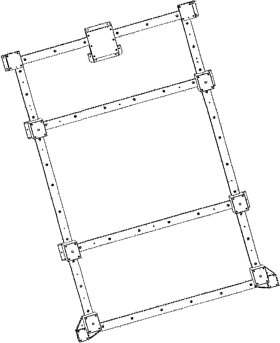
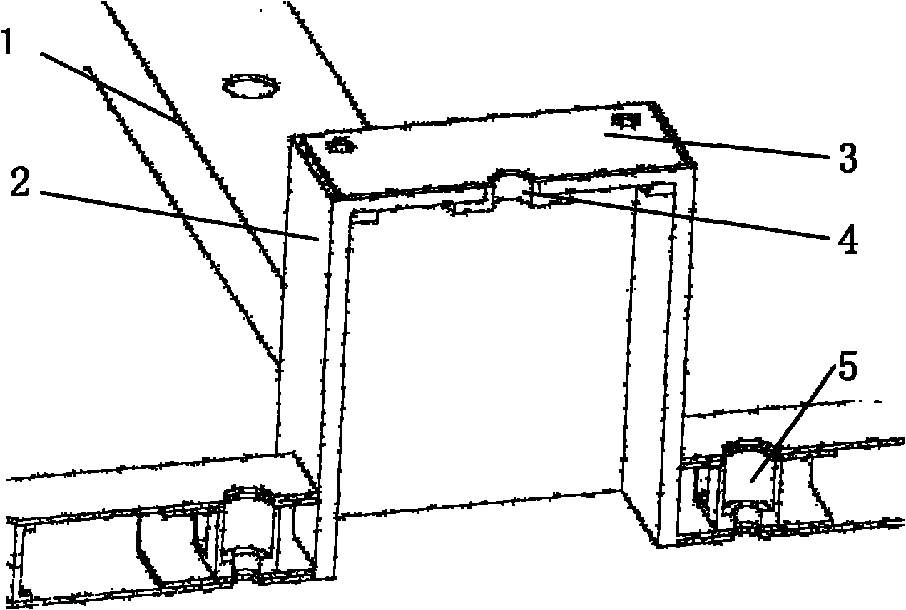
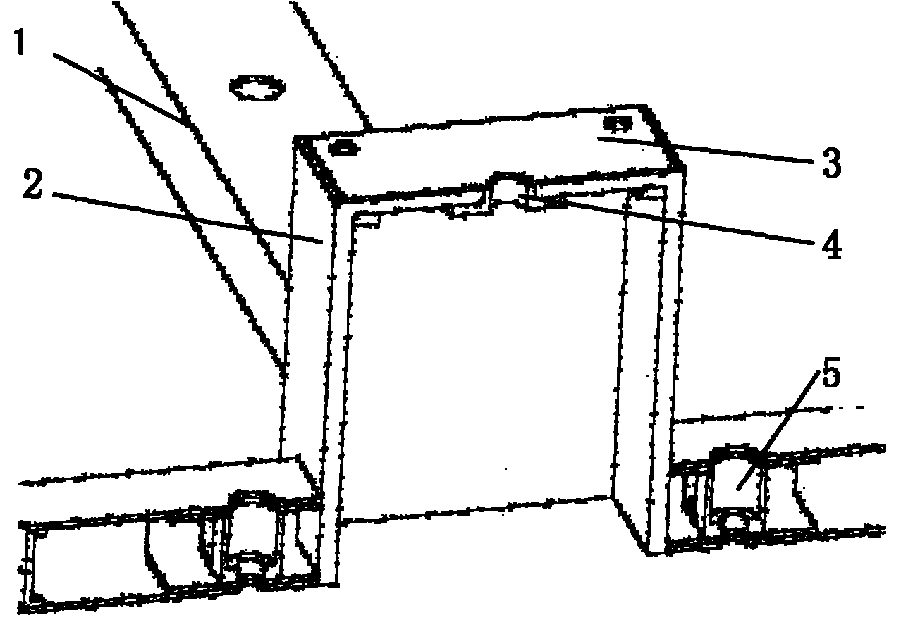
[0019] figure 1 It is a three-dimensional view of the light-duty high-precision composite material frame of the present invention, figure 2 It is a schematic diagram of the internal structure of the lightweight high-precision composite material frame of the present invention. As shown in the embodiment of the accompanying drawings, the device includes:

[0020] Rectangular section bar [1], joint [2], joint gasket [3], joint bushing [4], bar embedded part [5]; the whole structure consists of a certain number of rectangular section bars [1] and joints [2] Form the main body of the framework. The rod with rectangular cross section [1] is internally glued with a rod embedded part [5], the outer surface of the joint [2] is glued to the joint gasket [3], and the inner glued joint bushing [4].

[0021] The rectangular section bar [1] is a carbon / epoxy com


PUM

PropertyMeasurementUnit
Wall thicknessaaaaaaaaaa

Abstract

The invention relates to composite material frames for spacecrafts such as satellites and the like. The problem to be solved is to provide a method for realizing a light-weight high-accuracy composite material frame, and the high-accuracy requirement on the installation of effective loads is met through processes. The device is characterized by mainly comprising rectangle cross section rod pieces[1], joints [2], joint spacers [3], joint bushing blocks [4] and rod built-in pieces [5] which are made of composite materials, wherein a frame main body consists of a certain number of rectangle cross section rod pieces [1] and joints [2] in the integral structure; the rod built-in pieces [5] are hinged in the rectangle cross section rod pieces [1]; the joint spacers [3] are hinged on the outer surfaces of the joints [2]; and the joint bushing blocks [4] are hinged inside the joints [2]. By the method, the problems of installation and supporting between the effective loads and bodies of the spacecrafts such as the satellites and the like are solved, the installation accuracy of the effective loads is effectively ensured, and the local rigidity requirement on the installation of the effective loads is met simultaneously; and the method has good effects of ensuring the machining stability of the integral structure and improving the applicability and the reliability of the structure.

Description


Claims


Application Information

Patent Timeline
Owner SHANGHAI SATELLITE ENG INST
Why Eureka
Try Eureka