LED (Light-Emitting Diode) street lamp module

A technology for LED street lamps and LED components, which is applied in the cooling/heating devices of lighting devices, outdoor lighting, lighting and heating equipment, etc., can solve the problems of large heat, short-circuit use, and the waterproof structure cannot meet the requirements well, and achieves The effect of meeting the cooling requirements and improving the working life

Inactive Publication Date: 2012-09-05
苏州浩华光电科技有限公司
View PDF4 Cites 1 Cited by
  • Summary
  • Abstract
  • Description
  • Claims
  • Application Information

AI Technical Summary

Problems solved by technology

[0004] However, the current LED street lights will generate a lot of heat during work
More importantly, because the working environment of LED street lamps is in the open air, the existing wat

Method used


Image

  • LED (Light-Emitting Diode) street lamp module
  • LED (Light-Emitting Diode) street lamp module

Examples


Example Embodiment

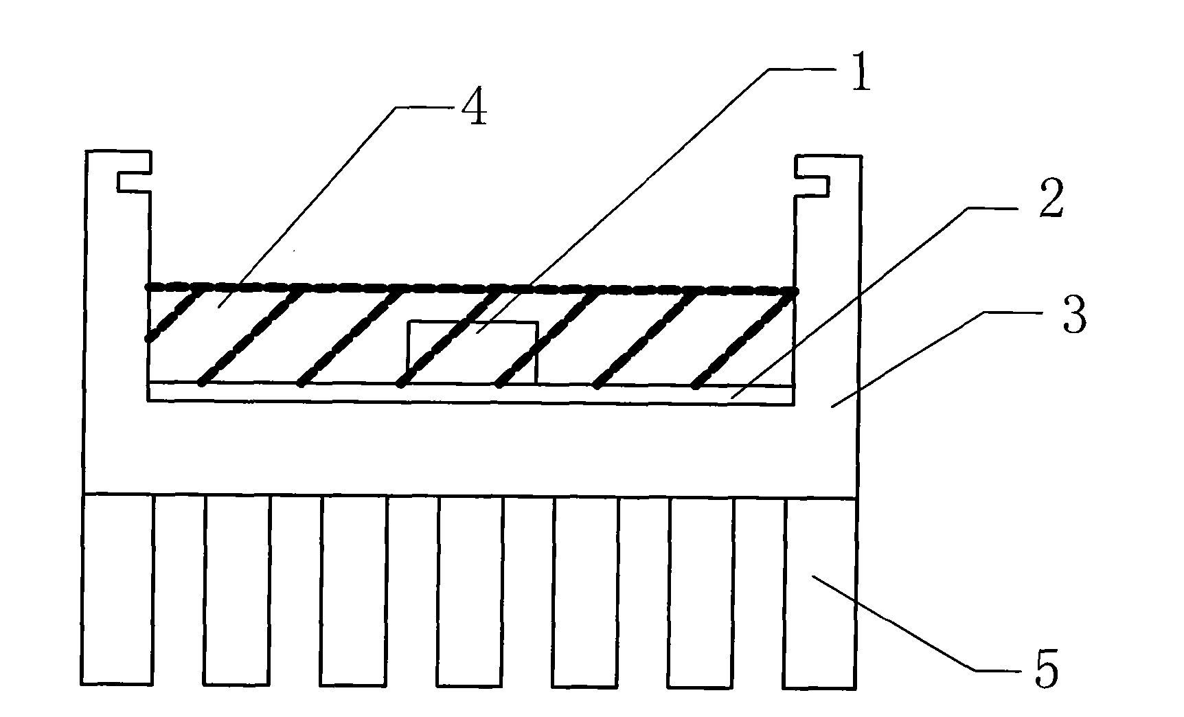
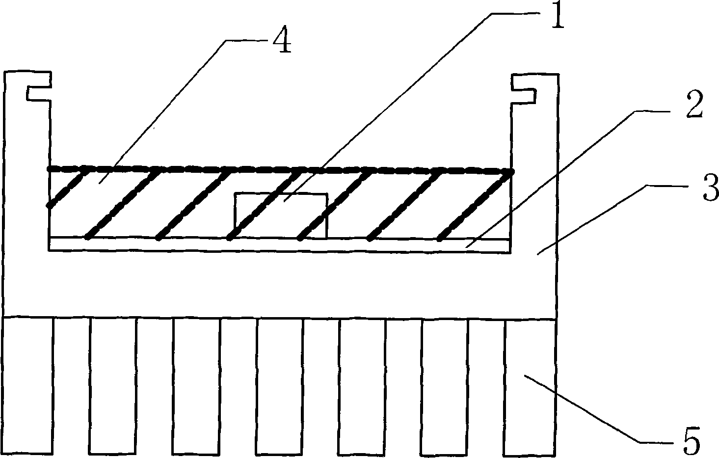
[0017] Such as figure 1 The shown LED street lamp module includes an LED component 1, which is particularly located in that a PCB board 2 is provided on the working surface of the LED component 1 used in the present invention. At the same time, a heat dissipation component 3 is installed on the PCB board 2. Looking further, receiving slots are distributed on the heat dissipation assembly 3, and the PCB is located in the receiving slots. In addition, a waterproof glue 4 is filled in the containing groove, and the LED assembly 1 and the PCB board 2 are located in the waterproof glue 4. Therefore, through the limitation of the receiving groove, it can be effectively ensured that the waterproof glue 4 is poured in place during the manufacturing process, and unnecessary overflow will not occur, and at the same time, there will be no lack of coverage of the LED assembly 1 or the PCB board 2.

[0018] In combination with a preferred embodiment of the present invention, in order to furthe


PUM


Abstract

The invention relates to an LED (Light-Emitting Diode) street lamp module which comprises an LED assembly. The LED street lamp module is characterized in that a PCB (Printed Circuit Board) is arranged on the working surface of the LED assembly, and a heat dissipation assembly is arranged on the PCB. Meanwhile, containing grooves are distributed on the heat dissipation assembly, and the PCB is arranged in the holding tanks. Furthermore, a waterproof adhesive is filled in the containing grooves, and the LED assembly and the PCB are located in the waterproof adhesive. Therefore, the LED assembly and the PCB can be effectively isolated from being in contact with outside water vapor, and the LED street lamp module can be mounted in various environments, especially in long-time humid areas. Thus, the heat dissipation requirements required when an LED street lamp works are met, and the service life of the LED street lamp is further prolonged.

Description


Claims


Application Information

Patent Timeline
Owner 苏州浩华光电科技有限公司
Why Eureka
Try Eureka