Method for preparing selective emitter through manner of one-time diffusion
A selective, one-off technology, applied in the direction of climate sustainability, final product manufacturing, sustainable manufacturing/processing, etc., can solve the problems of difficult mass production, complex production, high cost, etc., to reduce the preparation cost and simplify the preparation The effect of simple process and preparation process
- Summary
- Abstract
- Description
- Claims
- Application Information
AI Technical Summary
Benefits of technology
Problems solved by technology
Method used
Image

Examples
Embodiment 1
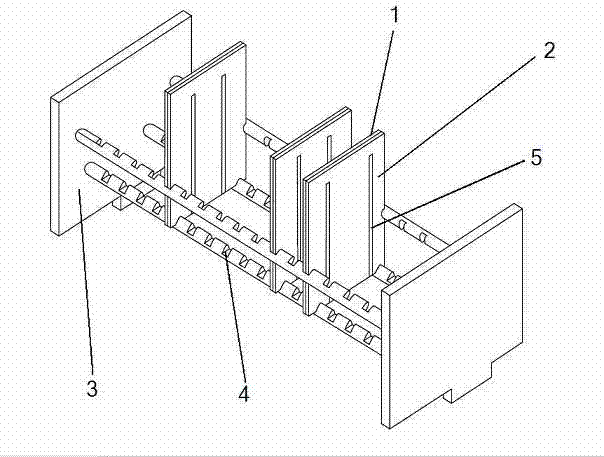
[0050] Insert a piece of silicon chip 1 and a piece of active selective diffusion template 2 with a thickness of 0.6 mm into the slot 4 on the split quartz boat 3 (see figure 1 ), the active selective diffusion template 2 has a hollow groove 5 with the same shape as the grid line printing pattern on the front of the silicon chip 1, and the width of the slot 4 is the thickness of the single silicon chip 1 and the single active selective diffusion template 2 Sum.
[0051] After loading the film, first pass a large N with a flow rate of 15L / min into the diffusion furnace 2 Raise the temperature of the diffusion furnace. When the temperature in the furnace rises to 800°C, push the split quartz boat 3 inserted with the silicon chip 1 into the diffusion furnace for 15 minutes, and then adjust the large N 2 The flow rate is 28L / min, so that the temperature in the furnace rises to and stabilizes at 844°C, and the heating rate is 2°C / min. When the temperature in the furnace is stab
Embodiment 2
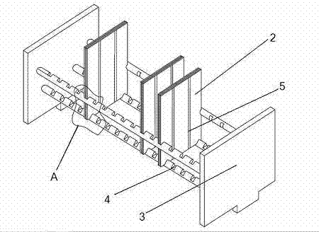
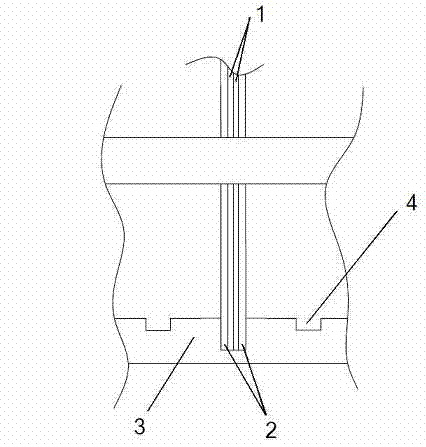
[0054] Two silicon wafers 1 with their backs attached to each other are sandwiched between two active selective diffusion templates 2 with a thickness of 1.2 mm (see image 3 ), inserted into the card slot 4 on the split quartz boat 3 after lamination, and a hollow slot 5 with the same shape as the grid line printing pattern on the front side of the silicon wafer 1 is opened on the active selective diffusion template 2 (see figure 2 ), the width of the slot 4 is the sum of the thicknesses of the two silicon chips 1 and the two active selective diffusion templates 2 .
[0055] After the film is loaded, a large N with a flow rate of 20L / min is introduced into the diffusion furnace first. 2 Heat up the diffusion furnace. When the temperature in the furnace rises to 805°C, push the split-type quartz boat 3 inserted with the silicon wafer 1 into the diffusion furnace for 17 minutes, and then adjust the large N 2 The flow rate is 25L / min, so that the temperature in the furnace ri
Embodiment 3
[0058] Insert a piece of silicon chip 1 directly into the slot 4 on the integrated quartz boat 7 (see Figure 5 ), one side of the card slot 4 is fixed with a fixed selective diffusion template 6 with a thickness of 1.2mm, the width of the card slot 4 is the thickness of a single silicon chip 1, and the fixed selective diffusion template 6 has a shape and a silicon chip 1 Hollow groove 5 with the same grid line printing pattern on the front (see Figure 4 ).
[0059] After loading the film, first pass a large N with a flow rate of 16L / min into the diffusion furnace 2 Raise the temperature of the diffusion furnace. When the temperature in the furnace rises to 810°C, push the integrated quartz boat 7 inserted with the silicon chip 1 into the diffusion furnace for 16 minutes, and then adjust the large N 2 The flow rate is 30L / min, so that the temperature in the furnace rises to and stabilizes at 850°C, and the heating rate is 3°C / min. When the temperature in the furnace is s
PUM
| Property | Measurement | Unit |
|---|---|---|
| Thickness | aaaaa | aaaaa |
Abstract
Description
Claims
Application Information
 - R&D Engineer
- R&D Manager
- IP Professional
- Industry Leading Data Capabilities
- Powerful AI technology
- Patent DNA Extraction
Browse by: Latest US Patents, China's latest patents, Technical Efficacy Thesaurus, Application Domain, Technology Topic.
© 2024 PatSnap. All rights reserved.Legal|Privacy policy|Modern Slavery Act Transparency Statement|Sitemap