Digital-to-analogue conversion method based on PWM (pulse width modulation) pin of DSP (digital signal processor)

A technology of digital-to-analog conversion and conversion method, which is applied in the direction of digital-to-analog converters, etc., and can solve problems such as bombing, problems, and increased costs

Inactive Publication Date: 2013-02-06
XIAN LONTEN RENEWABLE ENERGY TECH
View PDF3 Cites 2 Cited by
  • Summary
  • Abstract
  • Description
  • Claims
  • Application Information

AI Technical Summary

Problems solved by technology

[0002] In the digital control circuit, many control algorithms are implemented in the digital signal processor (DSP), the input variable is sent to the DSP, and the output variable is obtained after calculation, but in the debugging process of the circuit, it is often necessary to see the intermediate In order to debug whether the algorithm is correct or not, the general DSP programming environment will provide the function of online simulation, and the waveform of the intermediate variable can be viewed from the computer through the

Method used


Image

  • Digital-to-analogue conversion method based on PWM (pulse width modulation) pin of DSP (digital signal processor)
  • Digital-to-analogue conversion method based on PWM (pulse width modulation) pin of DSP (digital signal processor)
  • Digital-to-analogue conversion method based on PWM (pulse width modulation) pin of DSP (digital signal processor)

Examples


Embodiment Construction

[0021] The present invention will be described in detail below in conjunction with the accompanying drawings and specific embodiments.

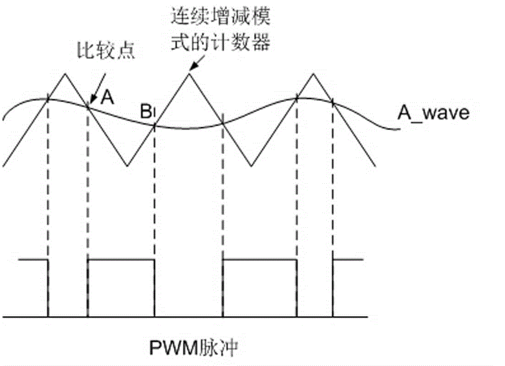
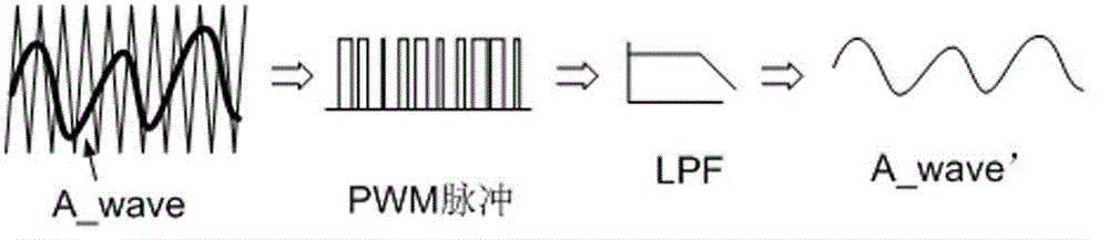
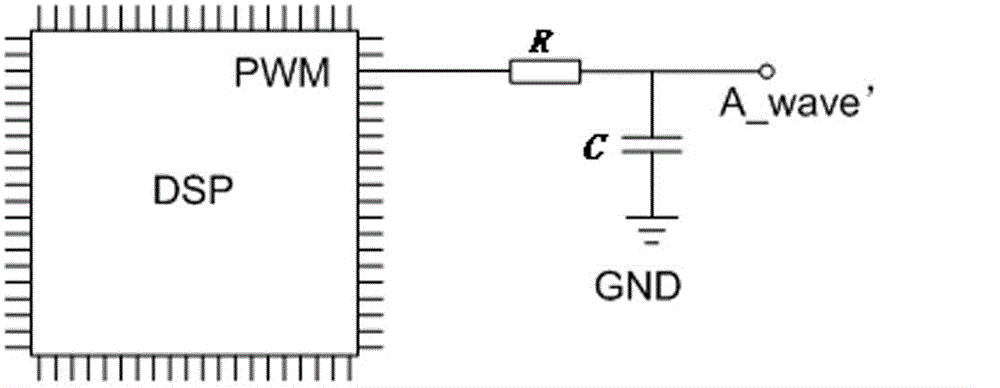
[0022] see Figure 1-3 , the present invention connects resistance R at PWM pin output inside DSP, connects a capacitance C between resistance R and circuit GND, and the common connection point of resistance R and capacitance C is output; Inside DSP, digital quantity A_wave is a time The quantity that has been discretized in terms of magnitude and amplitude, if the digital quantity corresponding to each time point is assigned to the comparison register inside the DSP, then the value in the counter (defined as the continuous increase and decrease counting mode) is equal to When the digital quantity of A_wave at this moment (this value is called the comparison match point), the specified PWM pin will output the corresponding level. see figure 1 It is stipulated that the output PWM pin is set to high level when the comparison matching point A is


PUM


Abstract

The invention relates to a digital-to-analogue conversion method based on a PWM (pulse width modulation) pin of a DSP (digital signal processor). The PWM pin in the DSP outputs a contact resistor R, a capacitor C is connected between the resistor R and a circuit GND (ground), and a public connecting point of the resistor R and the capacitor C serves as output; a signal requiring digital-to-analogue conversion is compared with a compare register in the DSP by the PWM pin in the DSP so as to obtain a high-frequency pulse waveform corresponding to the signal from the PWM pin, and then a waveform which is very close to the original signal can be obtained through the filter of the pulse waveform. According to the method, the analog of digital signals can be realized on the basis that the hardware cost is not increased nearly, and the complicated algorithm is not needed, and therefore, the danger caused by the online simulation run does not exist.

Description


Claims


Application Information

Patent Timeline
Owner XIAN LONTEN RENEWABLE ENERGY TECH
Why Eureka
Try Eureka