Transparent cover plates of heat engine track
- Summary
- Abstract
- Description
- Claims
- Application Information
AI Technical Summary
Benefits of technology
Problems solved by technology
Method used
Image

Examples
Embodiment Construction
[0013] The present invention will be described in detail below in conjunction with the accompanying drawings.
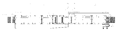
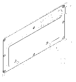
[0014] figure 1 , 2 , 3 shows a schematic view of the structure of the feed rail cover. In the figure, side plates are fixed on both sides of the track, forming a U-shaped structure with the track as the bottom surface; a layer of transparent and sealed cover plates are respectively covered on the discharge, cooling, crystal bonding, and feeding positions of the track, namely The discharge cover plate 4, the cooling structure cover plate 5, the crystal bonding structure cover plate 6 and the feed cover plate 7, one end of these sealing cover plates is stuck on the U-shaped groove of the side plate on one side of the track, and the other side is fixed on the The side plate on the other side of the track; the sealing cover is composed of a base 11, a heat-resistant glass 12, a sealing cover 13 and a sliding piece 14; a high-quality heat-resistant glass 12 is embedded in
PUM
 Abstract
Description
Claims
Application Information
 - R&D Engineer
- R&D Manager
- IP Professional
- Industry Leading Data Capabilities
- Powerful AI technology
- Patent DNA Extraction
Browse by: Latest US Patents, China's latest patents, Technical Efficacy Thesaurus, Application Domain, Technology Topic.
© 2024 PatSnap. All rights reserved.Legal|Privacy policy|Modern Slavery Act Transparency Statement|Sitemap