Drilling and milling cutter

A technology for drilling and milling cutters and blades, which is applied in the direction of milling cutters, drill repairing, milling machine equipment, etc., can solve the problems of low processing efficiency and time-consuming, and achieve the effects of improving production efficiency, saving man-hours, and reducing cutting volume

Inactive Publication Date: 2013-03-27
KINGHWA TOPTRUE WHEEL
View PDF0 Cites 2 Cited by
  • Summary
  • Abstract
  • Description
  • Claims
  • Application Information

AI Technical Summary

Problems solved by technology

[0002] After the casting of the aluminum alloy rim blank of the automobile wheel hub is completed, it is necessary to cut off the parts left by the redundant gating system, such as the center riser, side riser, and gate. The existing method is to use a twist

Method used


Image

  • Drilling and milling cutter

Examples


Example Embodiment

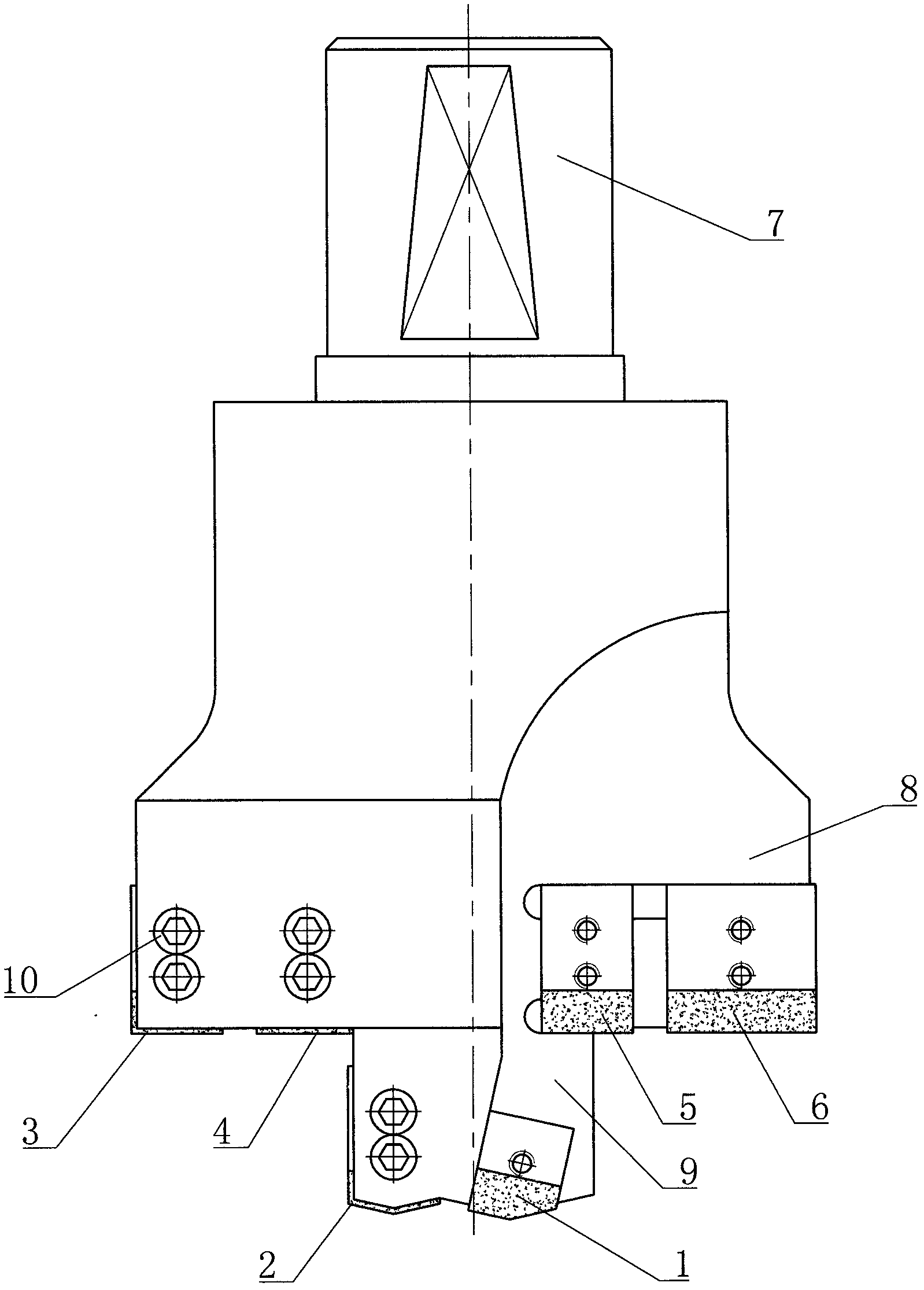
[0007] figure 1 Shown in is a specific embodiment of the present invention. A drilling and milling cutter of the present invention includes blade I, blade II, blade III, blade IV, blade V, blade VI, shank 7 and eleven hexagon socket screws 10 , There is a big boss 8 on the arbor 7 and a small boss 9 below the big boss 8. The blade I and the blade II are respectively mounted on the small boss 9 through the hexagon socket screws 10 at 180 degrees opposite each other. III. Blade IV, blade V, and blade VI are respectively installed on the large boss 8 through hexagon socket screws 10 at 180 degrees to each other. Blade III and blade IV are installed in the same direction, and blade V and blade VI are installed in the same direction. Blade I, blade II, blade III, blade IV, blade V, and blade VI are all cemented carbide blades.


PUM


Abstract

The invention relates to a drilling and milling cutter which comprises a blade I (1), a blade II (2), a blade III (3), a blade IV (4), a blade V (5), a blade VI (6), a cutter bar (7) and eleven socket head cap screws (10). A large boss (8) is arranged on the cutter bar (7), a small boss (9) is arranged under the large boss (8), the blade I (1) and the blade II (2) form a 180-degree angle respectively through the socket head cap screws (10) and are oppositely installed on the small boss (9), and the blade III (3), the blade IV (4), the blade V (5) and the blade VI (6) respectively form a 180-degee angle through the socket head cap screws (10) and oppositely installed on the large boss (8). The drilling and milling cutter is simple in structure, high in machining efficiency, low in cost, long in service life and used for machining aluminum alloy rims of automobile hubs.

Description


Claims


Application Information

Patent Timeline
Owner KINGHWA TOPTRUE WHEEL
Why Eureka
Try Eureka