Combined compressor multielement penetration compound layer piston ring

A multi-component co-infiltration and compound layer technology, which is applied in the field of compressors, can solve the problems of affecting the sealing performance of compressors, failure to obtain initial elasticity, large gaps, etc., and achieve the effect of improving service life, good performance and prolonging service life

Active Publication Date: 2014-04-02
成都展望能源机械有限公司
View PDF7 Cites 2 Cited by
  • Summary
  • Abstract
  • Description
  • Claims
  • Application Information

AI Technical Summary

Problems solved by technology

[0004] Regarding the sealing of the piston ring, if the outer edge of the piston ring is to closely fit the cylinder mirror surface, the piston ring must obtain a certain effective elasticity, so the piston ring must be made with a cut; if the piston ring does not have a cut, it cannot obtain the initial Elasticity, the piston ring does not necessarily stick to the mirror surf

Method used


Image

  • Combined compressor multielement penetration compound layer piston ring
  • Combined compressor multielement penetration compound layer piston ring
  • Combined compressor multielement penetration compound layer piston ring

Examples


Embodiment 1

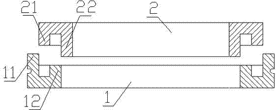
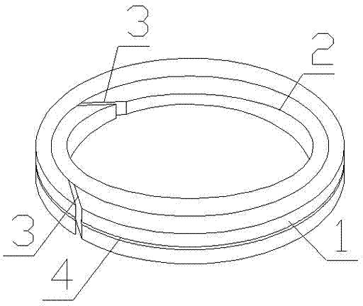
[0018] Such as figure 1 As shown, a combined multi-component compound layer piston ring of a compressor includes a main piston ring 1 and an inner auxiliary piston ring 2 . The main piston ring 1 and the inner auxiliary piston ring 2 have the same height, and both include a body made of polytetrafluoroethylene and polyether ether ketone filled in the body. The primary piston ring 1 and the inner secondary piston ring 2 are provided with a cutout 3, and the two cutouts 3 are arranged in a staggered manner. The middle part of the upper end surface of the main piston ring 1 is recessed inward to form a groove, forming a main piston ring 1 with an outer ring side 11 and an inner ring side 12, wherein the height of the outer ring side 11 of the main piston ring 1 is 12 on the inner ring side 2 times the height value, the height value of the inner ring side 12 is equal to the distance value between the outer ring side 11 and the inner ring side 12, and is also equal to the thickness v

Embodiment 2

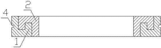
[0021] When the primary piston ring 1 and the inner auxiliary piston ring 2 in the first embodiment are assembled, the inner ring side 12 of the main piston ring 1 snaps into the groove between the outer ring side 21 and the inner ring side 22 of the inner auxiliary piston ring 2 Inside, the outer ring side 21 of the inner secondary piston ring 2 snaps into the groove between the outer ring side 11 and the inner ring side 12 of the primary piston ring 1 . Due to the height value of the outer ring side 11 on the main piston ring 1, the height value of the inner ring side 12, the distance value between the outer ring side 11 and the inner ring side 12 and the groove between the outer ring side 11 and the inner ring side 12 The ratio of the thickness value of the ring is: 2:1:1:1, the height value of the outer ring side on the inner auxiliary piston ring 2, the height value of the inner ring side, the distance value between the outer ring side and the inner ring side and the oute


PUM

PropertyMeasurementUnit
Thicknessaaaaaaaaaa

Abstract

The invention discloses a combined compressor multielement penetration compound layer piston ring, comprising a main piston ring and an inner auxiliary piston ring which are equal in height and are combined for use, wherein notches and bosses corresponding to the notches are respectively formed on the main piston ring and the inner auxiliary piston ring; the bosses are located in the corresponding notches; the height value of the outer ring side of the main piston ring is two times the height value of the inner ring side; the height value of the outer ring side of the inner auxiliary piston ring is a half of the height value of the inner side ring; the thickness values of the inner ring sides and the outer ring sides of the main piston ring and the inner auxiliary piston ring are identical and are equal to the distance value between the outer ring sides and the inner ring sides; a multielement penetration compound layer with the thickness of 0.08-0.12 mm is arranged on the outer cylindrical surface of the main piston ring; a polytetrafluoroethylene not-sticky coating is arranged on the multielement penetration compound layer; the two notches are arranged in a staggered way. The combined compressor multielement penetration compound layer piston ring is characterized in that a U-shaped unloading groove is formed in the outer cylindrical surface of the main piston ring. The piston ring can be used for effectively sealing the gap between the notches, and the sealing property of the piston ring is improved.

Description


Claims


Application Information

Patent Timeline
Owner 成都展望能源机械有限公司
Why Eureka
Try Eureka