Rapid testing device for toughness of thermal spraying coating and utilization method

A test device and thermal spraying technology, applied in the direction of testing the strength of materials by applying a stable bending force, can solve the problems of poor test repeatability, complex testing, uneven loading, etc., and achieve safe and reliable test results, fast and accurate testing, and manufacturing low cost effect

Inactive Publication Date: 2014-04-23
JIANGHAN MASCH RES INST LTD CO OF CNPC
View PDF6 Cites 7 Cited by
  • Summary
  • Abstract
  • Description
  • Claims
  • Application Information

AI Technical Summary

Problems solved by technology

[0003] At present, the viscose method is mainly used to test the binding force. For details, refer to GB/T8642-2002. Although this method can quantitatively test the binding force, due to the high requirements for the sample, poor test repeatability, and long cycle, Therefore not suitable for rapid test assessment
For the toughness test of thermal spray coatings, there are mainly drop hammer method, indentati

Method used


Image

  • Rapid testing device for toughness of thermal spraying coating and utilization method
  • Rapid testing device for toughness of thermal spraying coating and utilization method
  • Rapid testing device for toughness of thermal spraying coating and utilization method

Examples


Embodiment Construction

[0028] In order to make the object, technical solution and advantages of the present invention clearer, the present invention will be further described in detail below in conjunction with the accompanying drawings and embodiments. It should be understood that the specific embodiments described here are only used to explain the present invention, not to limit the present invention. In addition, the technical features involved in the various embodiments of the present invention described below can be combined with each other as long as they do not constitute a conflict with each other.

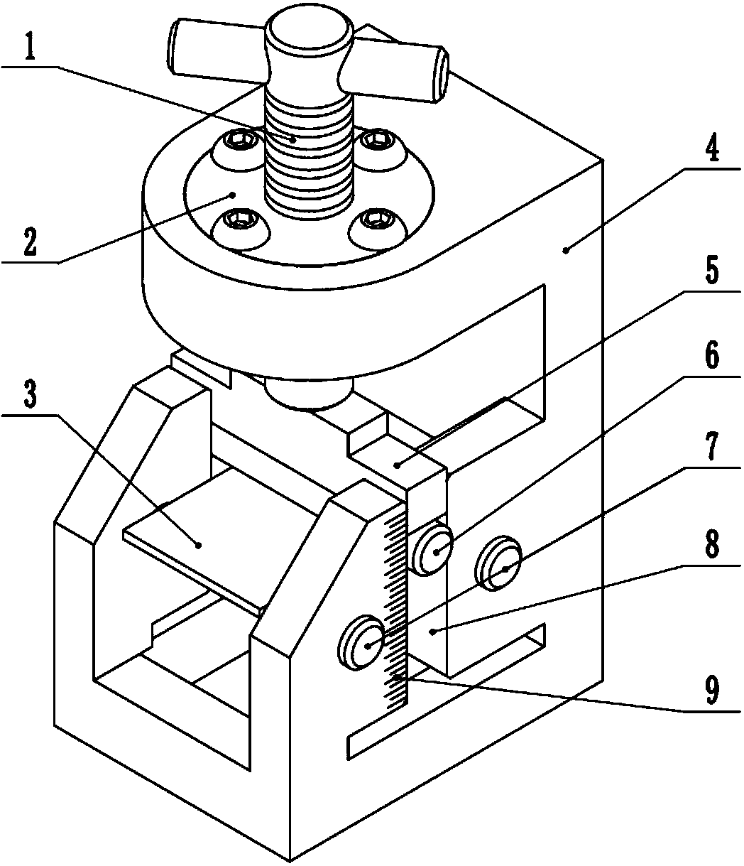
[0029] like figure 1 As shown, it is a structural schematic diagram of a small thermal spray coating toughness quick test device of the present invention, said device includes a base 4, a guide groove 8, a pressure screw 1, a pressure block 5, a pressure rod 6 and a support rod 7, of which:

[0030] The base 4 includes two opposite end faces and a connection face connecting the two end faces;


PUM


Abstract

The invention discloses a rapid testing device for the toughness of a thermal spraying coating. The rapid testing device comprises a base, a guide groove, a pressurizing screw rod, a pressurizing block, a pressurizing rod and a supporting rod, wherein the base comprises two end faces which are connected oppositely and a connection face for connecting the two end faces; a groove body capable of containing a coating test piece is formed in the inner side of one end face; a guide groove with the direction which is the same as the connection direction of the two end faces is formed in the side wall of the groove body; two through holes which are symmetrically distributed on the two sides of the guide groove are formed in the side wall of the groove body; the through holes are used for accommodating the supporting rod; the pressurizing screw rod is mounted on the other end face; the pressurizing screw rod is fixedly connected with the pressurizing block; the pressurizing block is fixedly connected with the pressurizing rod; and the axial directions of the pressurizing block, the pressurizing rod and the supporting rod are the same and the pressurizing block, the pressurizing rod and the supporting rod are arranged in the guide groove. Meanwhile, the invention further provides a method for utilizing the device. According to the rapid testing device and the method, a phenomenon that a load is not uniform and the repeatability is poor can be avoided; and the binding force and the toughness of the thermal spraying coating are rapidly and simply tested.

Description


Claims


Application Information

Patent Timeline
Owner JIANGHAN MASCH RES INST LTD CO OF CNPC
Why Eureka
Try Eureka