Fuel oil conveying pipeline with muffling device

A sound-absorbing device and conveying pipeline technology, applied in the direction of pipes, rigid pipes, pipe components, etc., can solve problems such as loud noise, interruption of oil supply system, blockage of fuel injectors, etc., and achieve the effect of reducing noise and slowing down the flow rate

Inactive Publication Date: 2014-10-01
梅晓萌
View PDF10 Cites 0 Cited by
  • Summary
  • Abstract
  • Description
  • Claims
  • Application Information

AI Technical Summary

Benefits of technology

This technology has two main benefits - one that reduces sound during fluid transport by creating an alternate path for liquids through which they move slowly without generating too much pressure or causing turbulence. Another benefit is its ability to reduce noise caused when fluids pass over obstacles like pipes due to vibrations from machinery.

Problems solved by technology

The technical problem addressed by this patented technology relates to improving the performance of fuel injection systems used on vehicles without introducing any harmful impurities like oliymmers called dimmer liquor residue(dimming), polyoxyethanes commonly found inside plastic parts, nitrogen oxides, sulfur dioxide, hydrocarbons, etc., caused by incomplete combustion processes between these compounds and lubricants containing chlorine gas. This leads to deposits formed within the engine's components leading to blockages and potential safety hazards associated therewith. Additionally, current methods involve adding metal layers to prevent corrosive damage to certain areas near the valves.

Method used


Image

  • Fuel oil conveying pipeline with muffling device

Examples


Embodiment Construction

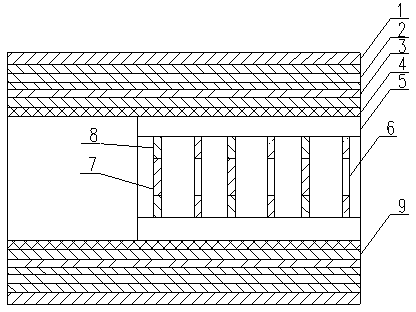
[0023] The technical solutions of the present invention will be further described below in conjunction with the accompanying drawings and through specific implementation methods.

[0024] Such as figure 1 As shown, the present application provides a fuel delivery pipeline with a noise reduction device, including a protective layer 1, a support layer 2, an isolation layer 3 and a low precipitation layer 4 arranged in sequence, wherein the liquid outlet end of the pipeline is arranged at A sound-absorbing device, the sound-absorbing device includes a casing 5 sleeved in the low precipitation layer 4, and alternately arranged first labyrinth plates 6 and second labyrinth plates 7 in the shell 5, the first labyrinth plates 6 are annular structures, The second labyrinth plate 7 is a disc structure, the outer edge of the first labyrinth plate 6 is fixed on the shell 5, the second labyrinth plate 7 is arranged on the middle part of the shell 5 by the connector 8, and the second labyrint


PUM


Abstract

The invention relates to the technical field of pipe fittings, in particular to a fuel oil conveying pipeline with a muffling device. The fuel oil conveying pipeline comprises a protection layer, a supporting layer, an isolation layer and a low-precipitation layer, the protection layer, the supporting layer, the isolation layer and the low-precipitation layer are sequentially arranged, the liquid outlet end of the pipeline is provided with the muffling device, the muffling device comprises a shell sleeved with the lower-precipitation layer, a first labyrinth plate and a second labyrinth plate, the first labyrinth plate and the second labyrinth plate are alternately arranged in the shell, the first labyrinth plate is of an annular structure, the second labyrinth plate is of a wafer structure, the periphery of the first labyrinth plate is fixed to the shell, the second labyrinth plate is arranged in the middle of the shell through a connector, and a gap allowing liquid to flow exists between the second labyrinth plate and the inner wall of the shell. Due to the fact that the first labyrinth plate and the second labyrinth plate which are distributed alternately are adopted, a roundabout liquid flow channel can be formed, and accordingly the flow speed of liquid is slowed down, and noise generated in the liquid flowing process is lowered.

Description


Claims


Application Information

Patent Timeline
Owner 梅晓萌
Why Eureka
Try Eureka