Method and device for detecting flow of carbon dioxide injected into oil field

A flow detection device, a technology for carbon dioxide, which is used in the measurement, production of fluids, and earth-moving drilling.

Inactive Publication Date: 2015-03-25
贵州航天凯山石油仪器有限公司
View PDF6 Cites 2 Cited by
  • Summary
  • Abstract
  • Description
  • Claims
  • Application Information

AI Technical Summary

Problems solved by technology

[0003] The object of the present invention is to provide a flow detection method and device for injecting carbon dioxide in an oil field, so as to solve the problem of test

Method used


Image

  • Method and device for detecting flow of carbon dioxide injected into oil field
  • Method and device for detecting flow of carbon dioxide injected into oil field
  • Method and device for detecting flow of carbon dioxide injected into oil field

Examples


Embodiment

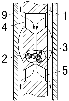
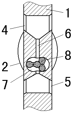
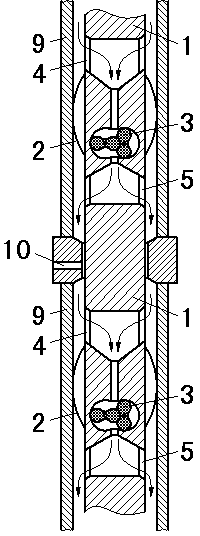
[0021] In this example, a downhole flowmeter is formed by connecting a waist wheel flowmeter in series with a collecting umbrella. The collecting umbrella can be opened or folded as required. When it is necessary to test the flow rate, first let the collecting umbrella open to seal with the inner wall of the oil pipe, and then measure the apparent flow rate at the current position by testing the rotation speed of the waist wheel. After measuring the apparent flow at the top and bottom of the same gas distributor, the actual gas injection volume of the layer to be measured can be obtained by subtracting the apparent flow at the bottom from the apparent flow at the top. In the present invention, two groups of flow collecting umbrellas and waist wheel flowmeters can also be arranged on the same downhole flowmeter. During the test, the positioning steps of the gas distribution device are used to control the two groups of flow collecting umbrellas to be located at the top and bottom


PUM


Abstract

The invention discloses a method and a device for detecting flow of carbon dioxide injected into an oil field. A detection instrument used by the method and the device is provided with a gas inlet and a gas outlet; a flow concentration umbrella is arranged at the excircle of the instrument between the gas inlet and the gas outlet; a roots flowmeter is arranged in the instrument between the gas inlet and the gas outlet. When the flow is detected, a gas passage outside an oil pipe is closed by the confluent-liquid umbrella, so that gas can be only exhausted from the gas outlet below the flow concentration umbrella by the gas inlet above the flow concentration umbrella after passing through the roots flowmeter; and according to the roots rotating speed of the roots flowmeter, apparent flux of a current position is measured. According to the invention, through cooperation of the flow concentration umbrella and the roots flowmeter, the problem of testing a layered filling rate of carbon dioxide in a supercritical state can be solved and the technological base is provided for realizing layered testing and regulation of a well filled with carbon dioxide.

Description


Claims


Application Information

Patent Timeline
Owner 贵州航天凯山石油仪器有限公司
Why Eureka
Try Eureka