Heat pump type double-cold-source liquid dehumidifier unit

A solution dehumidification, dual cold source technology, applied in the field of dehumidification equipment, heat pump dual cold source solution dehumidification unit, can solve the problems of difficult control of system operating parameters, low energy efficiency ratio, low efficiency, etc., to improve indoor air quality, avoid Effects of increased temperature, improved stability and accuracy

Active Publication Date: 2015-04-22
丛旭日 +1
View PDF6 Cites 4 Cited by
  • Summary
  • Abstract
  • Description
  • Claims
  • Application Information

AI Technical Summary

Benefits of technology

This patented technical effect described by this patents relates to improving thermal performance and reducing costs associated with conventional methods used for dehumiding warm sea waters. By utilizing both primary and secondary heat sources like solar radiation, direct sunlight absorption chambers, evaporative humidiol removal units, and membrane surfaces are able to efficiently remove moisture from these solutions while minimizing their production. Additionally, there is no need for external ice storage equipment due to its ability to store excessive amounts of salty brine without losing any significant quantities of stored material. Overall, this technology allows for efficient and reliable desalination processes over large areas such as coastlines where snow accumulation occurs frequently.

Problems solved by technology

This technical problem addressed in this patents relates to improving an air conditionion system's thermal management function without increasing power usage compared to existing methods like conventional ones. Current solutions involve adding ice/water mist accumulation tanks to adjust the temperatures and humids levels based solely upon ambient environmental factors. These techniques result in poor controllability and reduced operational efficacy because they rely heavily on external sources of electricity. Additionally, these processes may lead to contamination issues caused by impurities present within the atmosphere being treated.

Method used


Image

  • Heat pump type double-cold-source liquid dehumidifier unit
  • Heat pump type double-cold-source liquid dehumidifier unit
  • Heat pump type double-cold-source liquid dehumidifier unit

Examples


Embodiment Construction

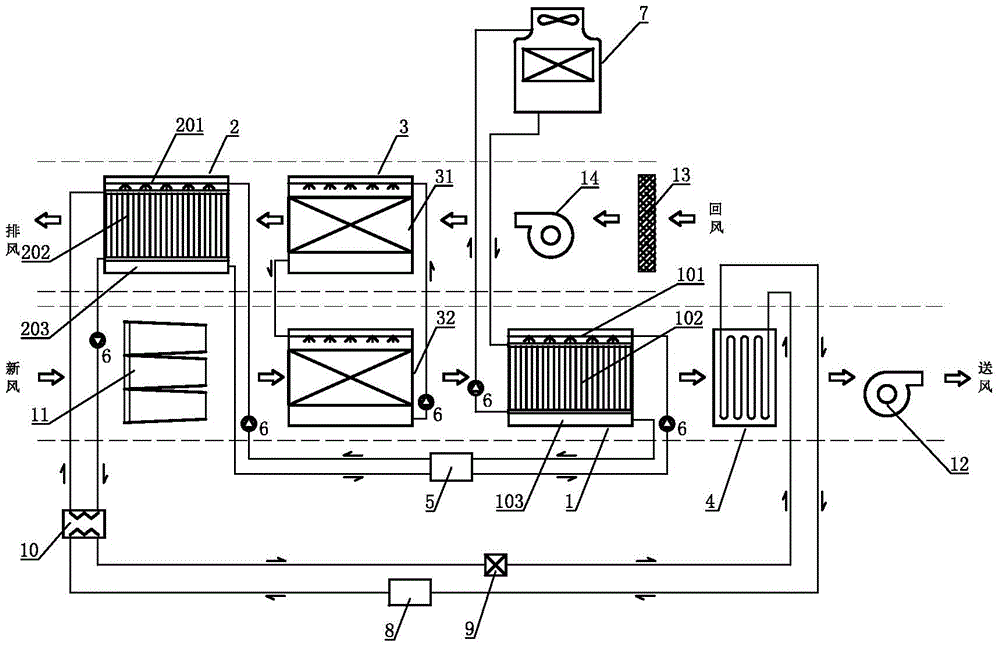
[0039] like figure 1 In the schematic diagram of the first embodiment of a heat pump double cold source solution dehumidification unit shown in the present invention, it includes a set of solution dehumidification units 1, a set of solution regeneration units 2, a set of solution heat recovery units 3, a surface cooler 4, the solution dehumidification unit 1 is provided with a first solution spraying device 101, a first heat exchange device 102, and a first solution tank 103 from top to bottom; the solution regeneration unit 2 is provided with a second solution spraying device from top to bottom Shower device 201, the second heat exchange device 202, the second solution tank 203; The solution heat recovery unit 3 includes the upper heat recovery device 31 and the lower heat recovery device 32 with the same structure, and the upper heat recovery device 31 and the lower heat recovery device 32 are respectively A third solution spraying device, a third heat exchange device, and a th


PUM


Abstract

The invention relates to a heat pump type double-cold-source liquid dehumidifier unit. The heat pump type double-cold-source liquid dehumidifier unit comprises at least one set of liquid dehumidification unit, at least one set of liquid regeneration unit, at least one set of liquid thermal recycling unit and at least one surface air cooler. The liquid thermal recycling unit comprises an upper thermal recycler and a lower thermal recycler with the same structure, the liquid dehumidification units and the liquid regeneration units are provided with liquid dehumidification and regeneration circulation loops, the liquid inlet and the liquid outlet of a first heat exchanging device in each liquid dehumidification unit are communicated with a cooling tower through a pipeline to form a first heat exchanging circulation loop, and the liquid inlet and the liquid outlet of a second heat exchanging device in each liquid regeneration unit are communicated through a pipeline to form a second heat exchanging circulation loop. The liquid inlet and the liquid outlet of the surface air cooler are sequentially communicated with a compressor, a condenser and an expansion valve in an end-to-end mode through a pipeline to form a heat pump circulation loop. The heat pump type double-cold-source liquid dehumidifier unit has the advantages of being stable in system, low in manufacturing and operating cost, high in energy efficiency ratio and accurate in control.

Description


Claims


Application Information

Patent Timeline
Owner 丛旭日
Why Eureka
Try Eureka