Microhole drilling system based on start-stop technology

A drilling and micro-hole technology, applied in the direction of boring/drilling, drilling/drilling equipment, large fixed members, etc., can solve the problem of inability to accurately control the hole depth, not suitable for metal parts cutting, low processing efficiency, etc. problems, achieve the effect of reducing labor intensity and technical requirements of workers, eliminating cutting chatter, and improving processing efficiency

Active Publication Date: 2015-07-08
南通海狮船舶机械有限公司
View PDF7 Cites 0 Cited by
  • Summary
  • Abstract
  • Description
  • Claims
  • Application Information

AI Technical Summary

Problems solved by technology

For laser processing, the laser can process holes with very small diameters, down to 0.001mm, which has incomparable advantages in the processing of brittle materials and polymer materials. The large angle and other characteristics have formed certain restrictions on the quality of micro-hole processing, and the energy utilization rate of laser processing is low, the processing cycle is long, and resources are seriously wasted. It is not suitable for the cutting processing of general metal parts.
The EDM method can process micropores with a minimum diameter of 0.08mm, but the micropore walls will leave a recast layer, which will affect the service life of the micropores and deteriorate the surface quality of the micropore walls.
The outstanding limitations of EDM are: it is mainly used to process metal conductive materials, and the general processing speed is relatively slow, the electrode is easy to burn the bottom of the microhole, and it is easy to produce processing taper
Manually feeding such a small-diameter drill requires skilled workers to feel manually, and use "feeling" to confirm whether the drill has been blunted or whether the drill is too fast, whether the depth of the hole meets the standard, etc., so the quality of the hole is not easy to guarantee. In severe cases, the drill bit may even be broken, making the workpiece scrapped, and the processing efficiency is low
[0004] Using special processing technologies such as the above-mentioned EDM, laser or electron beam processing and some new small hole processing methods are difficult to popularize due to the influence of processing quality or production cost
And drilling micro-holes still exist: manual processing requires high technical requirements for workers, the drill bit is easy to break, and the processing efficiency is low; the verticality of the workpiece cannot be guaranteed; it is difficult to move the workpiece for slightly large workpieces; the spindle speed is not high, and the hole is prone to burrs , the surface quality of the hole is not high; the hole depth cannot be precisely controlled, and special parts cannot meet the hole depth requirements and other technical bottlenecks

Method used


Image

  • Microhole drilling system based on start-stop technology
  • Microhole drilling system based on start-stop technology
  • Microhole drilling system based on start-stop technology

Examples


Example Embodiment

[0047] Example 1, see attached figure 1 ~ Attached Figure 8 , A micro-hole drilling system based on start-stop technology, including a base 9, a column fixed to the base 9, a support 3 fixed to the column 1, a drilling mechanism set on the support 3, The air cushion mechanism on the base 9, the three-way pressure sensor 6, the single-chip computer 19, and the distance measuring mechanism.

[0048] The drilling mechanism includes a vertical support shaft 20 movably set on the support 3, a rocker arm 16 set on the support shaft 20, a connecting plate 2 fixed on the support shaft 20, and a vertical support shaft fixed on the connecting plate 2. The electric spindle 4 passes through the support 3, and a chuck 5 is provided at the lower end of the electric spindle 4.

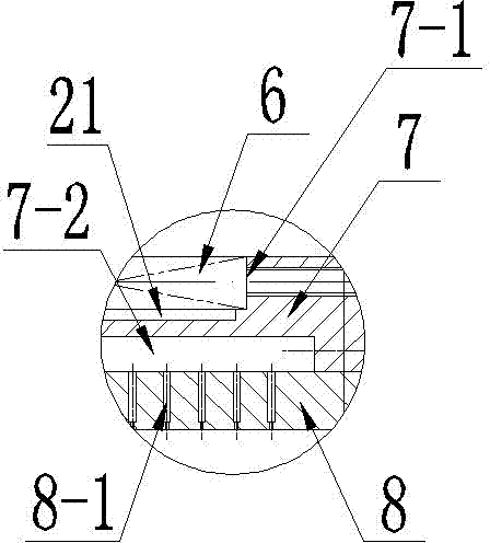
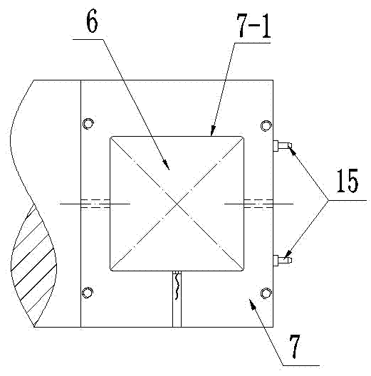
[0049] The air-cushion mechanism is located directly below the electric spindle 4. The air-cushion mechanism includes an air-cushion plate 8 on the base 9, a support plate 7 fixed to the upper end surface of the air-cushio


PUM


Abstract

The invention relates to a microhole drilling system based on a start-stop technology. The microhole drilling system comprises a base, a stand column, a support, a drilling mechanism arranged on the support, an air cushion mechanism arranged on the base, a three-direction pressure sensor and a single chip microcomputer. The drilling mechanism comprises a supporting shaft located on the support, a rock arm located on the supporting shaft, a connection plate located on the supporting shaft and an electric spindle located on the connection plate. The electric spindle penetrates through the support. The air cushion mechanism is located under the electric spindle and comprises an air cushion plate located on the base and a supporting plate fixed to the upper end face of the air cushion plate. The upper end face of the supporting plate is provided with a groove. The pressure sensor is fixed into the groove. The lower end face of the supporting plate is provided with an air circulation groove. One side of the supporting plate is provided with an air inlet nozzle communicated with the air circulating groove. The air cushion plate is densely provided with air vents communicated with the air circulating groove. By means of the microhole drilling system, machining efficiency can be improved, the labor intensity of workers and the technological requirement are lowered, cutting vibration is eliminated, the surface quality of holes is guaranteed, and the hole depth and drill bit position are monitored and controlled in real time.

Description


Claims


Application Information

Patent Timeline
Owner 南通海狮船舶机械有限公司
Why Eureka
Try Eureka