Solid fuel combustion device
A solid fuel and combustion device technology, which is applied in the field of solid fuel combustion, can solve the problems of no continuous combustion, can only be burned in the upper combustion chamber, and cannot be continuously burned, so as to achieve orderly and controllable combustion, solve potential safety hazards, and ensure full burn effect
- Summary
- Abstract
- Description
- Claims
- Application Information
AI Technical Summary
Benefits of technology
Problems solved by technology
Method used
Image

Examples
Embodiment 1
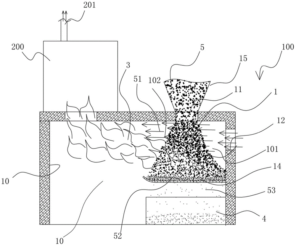
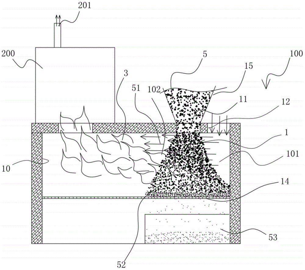
[0084] Figure 2 to Figure 5 It is the structural representation of embodiment 1. Such as Figure 2 to Figure 5 As shown, in this embodiment, no intermediate structure is provided between the side of the pile layer 1 located at the combustion side 102 and the combustion chamber 3 . Like this, when burning, wind carries the volatile matter 51 that separates out from the combustion side 102 of stockpiling layer 1 and flows toward combustion chamber 3, and volatile matter 51 is directly ignited by the combustion flame toward combustion chamber 3 combustion, enters combustion chamber 3 Combustion, the combustion tail gas is discharged from the tail gas outlet 201.
Embodiment 2
[0086] Figure 6 to Figure 11 It is the structural representation of embodiment 2. Such as Figure 6 to Figure 11 As shown, in this embodiment, a regenerator 21 is provided on the flow path of the volatile gas flow on the combustion side 102 . Like this, when burning, regenerator 21 is heated by combustion flame, has improved the temperature on the path that volatile matter 51 flows through, and after wind is with the volatile matter 51 that separates out from the combustion side 102 of stockpiling layer 1, volatile matter 51 is ignited by the high temperature generated by the heat storage body 21 and the combustion flame when flowing through the heat storage body 21, and enters the combustion chamber for combustion, thereby further improving the combustion efficiency of volatile matter.
[0087] In this embodiment, the heat accumulator 21 can be made of heat accumulator material, and can be heated by a side-burning flame, so as to form a high-temperature environment on the flo
Embodiment 3
[0091] Figure 12 to Figure 20 It is a schematic diagram of the structure of this embodiment. Such as Figure 12 to Figure 20 As shown, in this embodiment, a guide wall 22 is provided on the volatile flow path of the combustion side 102 to guide the volatile flow to the combustion flame. In this way, during the combustion process, the separated volatile matter passes through the combustion side of the stockpiling layer 1 and is guided to the position of the combustion flame by the deflector wall 22, thereby being ignited and entering the combustion chamber for combustion. Since the volatile matter 51 is guided through the guide wall 22, the volatile matter 51 must pass through the high temperature zone of the combustion flame, and thus be ignited by the high temperature generated by the combustion flame, further improving the combustion efficiency of the volatile matter.
[0092] In the present invention, the deflector wall 22 can be arranged in various forms, as long as it can
PUM
 Abstract
Description
Claims
Application Information
 - R&D Engineer
- R&D Manager
- IP Professional
- Industry Leading Data Capabilities
- Powerful AI technology
- Patent DNA Extraction
Browse by: Latest US Patents, China's latest patents, Technical Efficacy Thesaurus, Application Domain, Technology Topic.
© 2024 PatSnap. All rights reserved.Legal|Privacy policy|Modern Slavery Act Transparency Statement|Sitemap