Floor heating structural body and laying method thereof

A structure and floor heating technology, which is applied in heating methods, building structures, lighting and heating equipment, etc., can solve the problems of chaotic wiring of carbon fiber heating cables, reduce the height of buildings, and thick laying, so as to save materials and reduce construction period , the effect of thickness reduction

Inactive Publication Date: 2015-12-02
ZHANGJIAGANG KEXING CARBON FIBER PROD
View PDF6 Cites 2 Cited by
  • Summary
  • Abstract
  • Description
  • Claims
  • Application Information

AI Technical Summary

Problems solved by technology

[0004] In the prior art, the laying of electric floor heating is usually to lay a layer of heat insulation layer on the cement floor of the blank room, lay carbon fiber heating cables on the heat insulation layer, and then lay a c

Method used


Image

  • Floor heating structural body and laying method thereof
  • Floor heating structural body and laying method thereof
  • Floor heating structural body and laying method thereof

Examples


Embodiment Construction

[0020] The technical solution of the present invention will be described in further non-limiting detail below in combination with preferred embodiments and accompanying drawings.

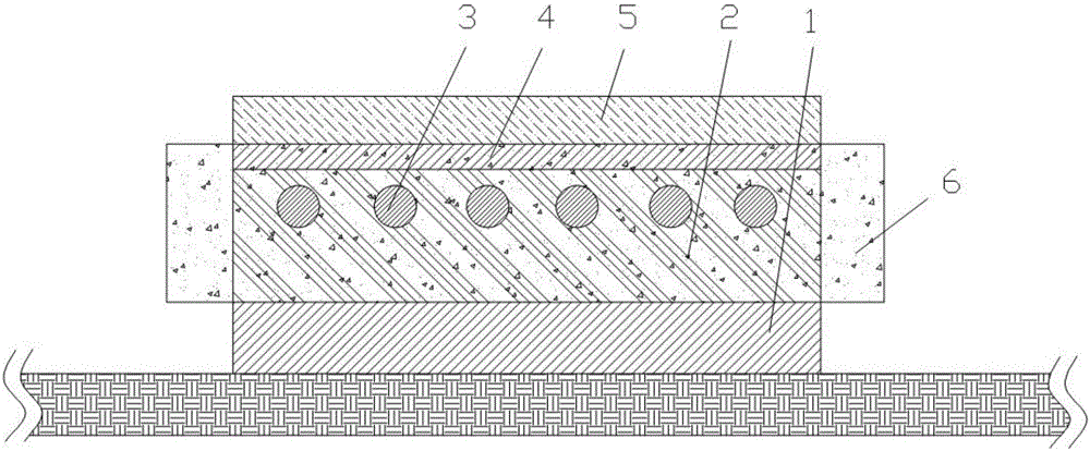
[0021] refer to figure 1 , which shows the floor heating structure of the present invention, which is laid on the ground or the base layer of the floor as a whole, and uses the heat storage and heat radiation of the ground itself to heat the entire ground, thereby increasing the temperature in a specific space. The floor heating structure includes a hard insulation layer 1, a laying layer 2, a cable net 3, a reinforced barbed wire 4, a ground decoration layer 5, and a cement layer 6 filled between the hard insulation layer 1 and the ground decoration layer 5.

[0022] Specifically, the hard insulation layer 1 is laid on the ground or the base layer of the floor, and is the supporting part of the entire floor heating structure, so its compressive capacity must be extremely high, otherwise it will cause


PUM

PropertyMeasurementUnit
Heightaaaaaaaaaa
Heightaaaaaaaaaa

Abstract

The invention discloses a floor heating structural body and a laying method thereof. The structural body comprises a hard thermal-insulation layer, a laying layer, a cable network, a reinforcement iron gauze, a ground decoration layer and a cement layer arranged between the hard thermal-insulation layer and the ground decoration layer in a filling mode. The layer method comprises the steps of stacking the hard thermal-insulation layer, the laying layer, the reinforcement iron gauze and the ground decoration layer in sequence; installing the cable network in the laying layer; and filling interiors of the laying layer and the reinforcement iron gauze with the cement layer. The floor heating structural body is orderly in wiring, and materials are saved; by the arrangement of the structural body and the cooperation of the corresponding laying method, the thickness of the structural body is reduced, use space is reduced, the heat efficiency is improved, the construction period is shortened, and the construction cost is reduced.

Description


Claims


Application Information

Patent Timeline
Owner ZHANGJIAGANG KEXING CARBON FIBER PROD
Why Eureka
Try Eureka