Cold spinning device used for steel seamless gas cylinder

A seamless gas cylinder and cold spinning technology, which is applied in the field of gas cylinder cold spinning processing equipment, can solve problems such as uneven force on the spinning wheel, and achieve the effect of eliminating surface wavy lines, good stability, and eliminating wavy lines

Active Publication Date: 2016-05-18
浙江金盾压力容器智造股份有限公司
View PDF7 Cites 1 Cited by
  • Summary
  • Abstract
  • Description
  • Claims
  • Application Information

AI Technical Summary

Benefits of technology

This patented technology improves upon existing methods for producing plastic containers used in cold-spinning processes. It includes three main components: an injection machine (also called spinner), a spinning roller assembly, and a support mechanism. These technical improvements improve the efficiency and effectiveness of these systems while reducing costs associated therewith.

Problems solved by technology

Technological Problem addressed in this patents relating to improving the performance of high pressure gas cylinding (HGP) valves used at home or abroad. Previous methods resulted in poor internal appearance and reduced strength compared to new designs that were being introduced into markets over time. Cold spray technology was proposed but had issues such as instability caused by friction from the roller and shake during operation. Therefore, an objective aimed to improve these technical problem areas involves finding ways to prevent damage and maintain stable products while reducing unwanted variations within acceptable levels.

Method used


Image

  • Cold spinning device used for steel seamless gas cylinder
  • Cold spinning device used for steel seamless gas cylinder
  • Cold spinning device used for steel seamless gas cylinder

Examples


Embodiment Construction

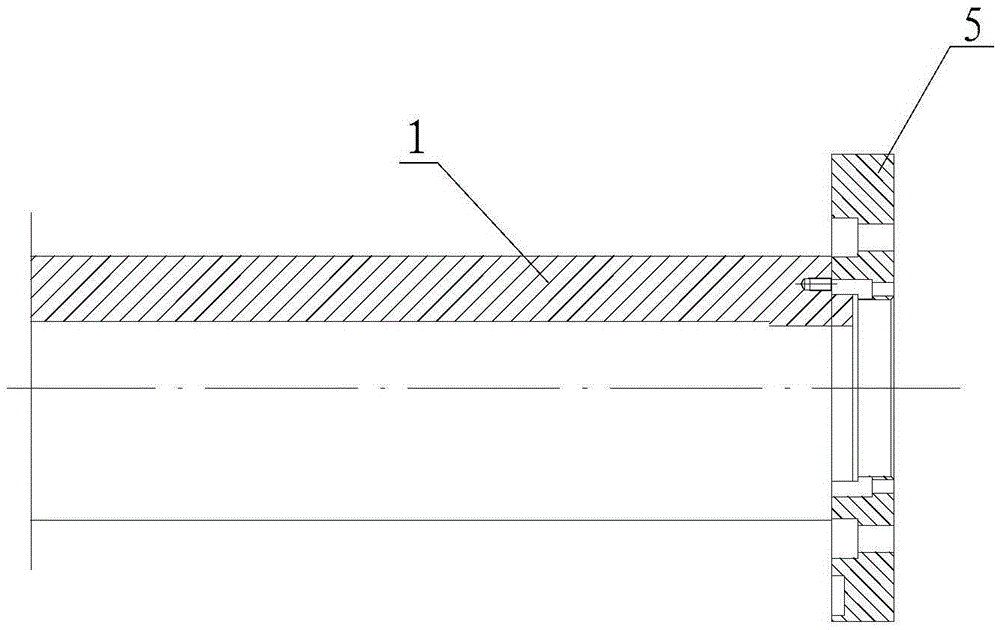
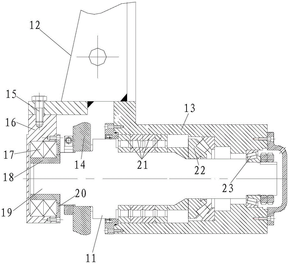
[0037] Such as Figure 3-6 As shown, a cold spinning device for steel seamless gas cylinders includes a mandrel 1 that extends into the preform to process the inner surface, a connecting assembly connected to the end of the mandrel 1, and a preform located outside the preform. Wheel assembly.

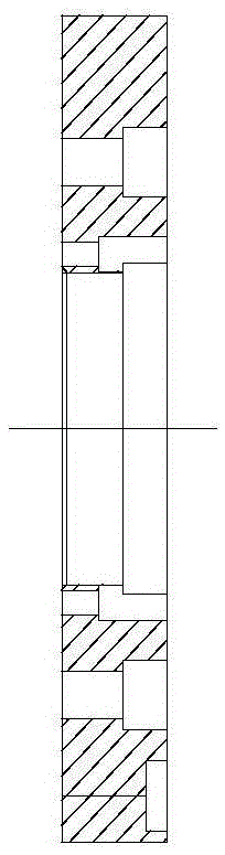
[0038] Such as image 3 and Figure 4 As shown, the rotary wheel assembly includes a rotary wheel bracket 12, a spinning shaft 11 rotatably fitted on the rotary wheel bracket 12, and a rotary wheel 14 sleeved on the spinning shaft 11 and pressed against the outer surface of the preform.

[0039] One end of the spinning shaft 11 stretches into the fixed wheel casing 13 with the wheel bracket 12, and the other end 19 stretches into the supporting overcoat 16 fixed with the spinning wheel bracket 12, and the spinning shaft 11 end in the supporting overcoat 16 is also The sleeve is provided with a support lining 18, and a double row of 6314 bearings 17 is provided between the support lining


PUM


Abstract

The invention discloses a cold spinning device used for a steel seamless gas cylinder. The cold spinning device comprises a core rod stretching in a cylinder blank to machine the inner surface, a connecting assembly connected to the end of the core rod, and a spinning wheel assembly located outside the cylinder blank. The spinning wheel assembly comprises a spinning wheel support, a spinning shaft rotationally arranged on the spinning wheel support in a matched manner, and spinning wheels arranged on the spinning shaft in a sleeving manner and abutting against the outer surface of the cylinder blank. One end of the spinning shaft stretches in a spinning wheel box body fixed to the spinning wheel support, and the other end of the spinning shaft stretches in an outer supporting sleeve fixed to the spinning wheel support. The end, in the outer supporting sleeve, of the spinning shaft is further sleeved with a supporting lining. Double rows of 6314 bearings are arranged between the supporting lining and the outer supporting sleeve. The part, stretching in the spinning wheel box body, of the spinning shaft is divided into a first shaft section, a second shaft section and a third shaft section, wherein the shaft diameter of the first shaft section, the shaft diameter of the second shaft section and the shaft diameter of the third shaft section are gradually decreased, the first shaft section is sleeved with a non-standard bearing, the second shaft section is sleeved with a thrust roller bearing and the third shaft section is sleeved with a tapered roller bearing. The connecting assembly comprises a connecting piece installed on a drive device and a butt joint located between the connecting piece and the core rod.

Description


Claims


Application Information

Patent Timeline
Owner 浙江金盾压力容器智造股份有限公司
Why Eureka
Try Eureka