Parallelogram law demonstrating instrument

A parallelogram and demonstration instrument technology, applied in the direction of instruments, educational tools, teaching models, etc., can solve the problems of difficulty in comprehension decomposition, inability to directly observe, discontinuity, etc., achieve high accuracy, good teaching and interpretation effect, reduce The effect of small experimental error

Pending Publication Date: 2016-08-17
HENAN NORMAL UNIV
View PDF4 Cites 0 Cited by
  • Summary
  • Abstract
  • Description
  • Claims
  • Application Information

AI Technical Summary

Problems solved by technology

Decomposition force is to better solve the calculation of some forces that cannot be directly solved. This original intention brings certain difficulties to the decomposition of students' comprehension. They cannot be directly imagined

Method used


Image

  • Parallelogram law demonstrating instrument

Examples


Example Embodiment

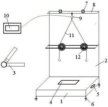
[0008] The specific content of the present invention will be described in detail with reference to the accompanying drawings. Parallelogram rule demonstration instrument, including a bottom plate 1 and a vertical plate 2 fixed on one side of the bottom plate 1. The upper part of the bottom plate 1 is provided with a placement slot 4 for placing the digital display angle ruler 3, and the left and right sides of the bottom plate 1 are equipped with level rules 5 , The bottom of the bottom plate 1 is provided with an adjusting leg 6, the top of the vertical plate 2 is fixed with a hanging plate 8 through a square clamp 7, the hanging end of the S-shaped tension sensor 9 is fixed to the middle of the hanging plate 8, and the S-shaped tension sensor 9 passes through the line Electrically connected to the display screen 10, the measuring end of the S-type tension sensor 9 is connected with two ropes 11, the ends of the two ropes 11 are respectively provided with hooks, and the middle par


PUM


Abstract

The invention discloses a parallelogram law demonstrating instrument which comprises a bottom plate and a vertical plate fixed to one side of the bottom plate, wherein a drawing is fixed to the top of the vertical plate through a square clamp, a hanging end of an S-shaped tension sensor is fixed to the middle of a hanging plate, two ropes are connected to a measuring end of the S-shaped tension sensor, hangers are arranged at the tail ends of the two ropes respectively, a slide way with the extension direction consistent with that of the hanging plate is arranged in the middle of the vertical plate, two pulleys capable of moving left and right along the slide way are fixed onto the slide way through pin shafts, one end of each pin shaft penetrates the vertical plate and is locked by a nut, the two ropes are wound on the pulleys respectively, and weights are arranged on the hangers at the tail ends of the ropes. The parallelogram law demonstrating instrument has the advantages of convenience in use, novel structure and high accuracy.

Description


Claims


Application Information

Patent Timeline
Owner HENAN NORMAL UNIV
Why Eureka
Try Eureka