Nine-block box modular design method for robot plate deploying and retracting machine

A technology of modular design and robotics, applied in the direction of conveyor objects, transportation and packaging, etc., can solve the problems of reducing design efficiency, increasing costs, and confusing equipment layout, and achieve the effect of improving design efficiency and reducing R&D costs

Active Publication Date: 2016-09-21
SHANGHAI KAISER ELECTRONICS
View PDF5 Cites 0 Cited by
  • Summary
  • Abstract
  • Description
  • Claims
  • Application Information

AI Technical Summary

Problems solved by technology

[0003] (1) The product layout is chaotic, there is no systematic design concept, and it is impossible to form a series of products
The needs of the customer's factory are different, because there is no good design release as a guide, resulting in confusion in the layout of the equipment
[0004] (2) The design workload is heavy and the design cost is high
Due to disor

Method used


Image

  • Nine-block box modular design method for robot plate deploying and retracting machine
  • Nine-block box modular design method for robot plate deploying and retracting machine
  • Nine-block box modular design method for robot plate deploying and retracting machine

Examples


Embodiment Construction

[0023] The present invention will be described in detail below in conjunction with the accompanying drawings and embodiments.

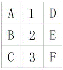
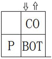
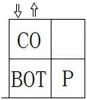
[0024] A nine-square modular design method for a robot retractable trigger, characterized in that the method includes the following steps: A, designing each component in the robot retractable trigger into a standardized module, and the components of the robot retractable trigger include A robot and adsorption system, a conveying section assembly, and at least one PCB carrier placement platform, each of which is designed as a first-type module or a second-type module, the first-type modules have the same size, and the second-type modules have the same Dimensions, the robot, the adsorption system, and the conveying section components are the second type modules, and the PCB carrier placement platform is the first type module or the second type module; B. Arrange the components of the robot retractable trigger into 3 rows The nine-square grid layout of colu


PUM


Abstract

The invention discloses a nine-block box modular design method for a robot plate deploying and retracting machine. The method comprises the following steps that A, all assemblies in the robot plate deploying and retracting machine are designed to be standard modules and comprise a robot, a suction system, a conveying section assembly and a PCB carrier placing platform, and all the assemblies are designed to be first type modules or second type modules, wherein the first type modules have the same dimension and the second type modules have the same dimension; B, the assemblies of the robot plate deploying and retracting machine are arranged in the mode of a nine-block box with three lines and three rows, wherein the first type modules are arranged in the two rows on the two sides, and the second type modules are arranged in the middle row. According to the nine-block box modular design method, the systematized and modular design concept is used for simplifying the design process of the robot plate deploying and retracting machine, a system arrangement mode is formed, the design efficiency is greatly improved, and the development cost is lowered.

Description


Claims


Application Information

Patent Timeline
Owner SHANGHAI KAISER ELECTRONICS
Why Eureka
Try Eureka