Certificate card holder
A technology for ID cards and card sleeves, applied in the field of card sleeves, can solve the problems of injection molding card hook injection defects, poor elastic deformation of the card hook, poor use stability, etc., and achieves low cost, good use stability, and high use stability. Effect
- Summary
- Abstract
- Description
- Claims
- Application Information
AI Technical Summary
Benefits of technology
Problems solved by technology
Method used
Image

Examples
Embodiment 1
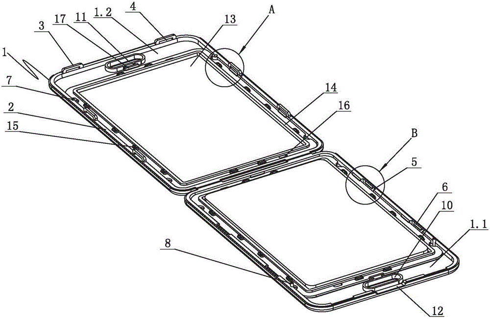
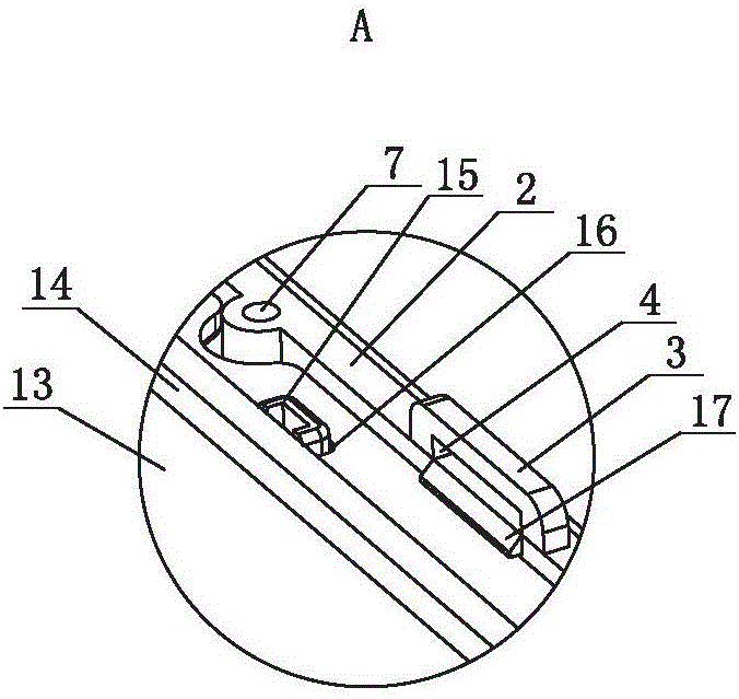
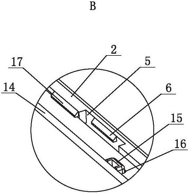
[0025] Such as figure 1 , figure 2 , image 3 , Figure 4 and Figure 5 As shown, a document card holder, which includes a body 1, the body 1 is a vertical document card holder, that is, the hook hole is set at one end of the length direction of the body 1, and the vertical direction is the length direction of the body 1, and the body 1 It is divided into a panel 1.1 and a back panel 1.2, the panel 1.1 is connected to the back panel 1.2, and there is a gap for accommodating the ID card between the panel 1.1 and the back panel 1.2, the surface of the panel 1.1 opposite to the back panel 1.2 and the The surface of the back plate 1.2 opposite to the panel 1.1 is provided with first protrusions 2 extending along the edge. The edges of the board 1.2 are flush, and both sides of the backplane 1.2 opposite to the panel 1.1 are provided with clamping blocks 3, generally two clamping blocks 3 are provided on each side, and the clamping blocks 3 are located at the first On a protrusi
Embodiment 2
[0035] Such as Figure 6 As shown, a document card holder, which includes a body 1, the body 1 is a horizontal document card holder, that is, the hook hole is set at one end of the width direction of the body 1, and the transverse direction is the length direction of the body 1; the body 1 is a frame type Structure, the body 1 is divided into two halves along the thickness direction, the panel 1.1 and the back panel 1.2, the panel 1.1 is connected to the back panel 1.2, and there is a gap for accommodating the ID card between the panel 1.1 and the back panel 1.2, the panel 1.1 and the back panel 1.2 There are openings 9 on the backboard 1.2, and the openings 9 are square openings. The first mounting hole 10 and the second mounting hole 11 are respectively provided on the panel 1.1 and the backboard 1.2, and the first mounting hole 10 and the second mounting hole The hooking holes 11 are arranged oppositely and correspond to each other. After the panel 1.1 and the backboard 1.2 ar
Embodiment 3
[0045] Such as Figure 7 As shown, a card holder for a certificate, which includes a body 1, the body 1 is a vertical certificate card holder, that is, the hooking hole is set at one end of the length direction of the body 1, and the body 1 is divided into a panel 1.1 and a backboard 1.2. The panel 1.1 is connected to the back panel 1.2, and there is a gap for accommodating the ID card between the panel 1.1 and the back panel 1.2, and a first protrusion extending along the edge is provided on the surface opposite to the panel 1.1 and the back panel 1.2 2. The first protrusion 2 on the panel 1.1 can also be understood as the side walls around the panel 1.1 after the accommodating cavity is set, which is the first protrusion 2, and the two sides of the opposite surface of the panel 1.1 and the back plate 1.2 Each side is provided with a clamping block 3, and the clamping block 3 is provided with a clamping hole 4 on the side, and the clamping hole 4 is a square hole, and the hole w
PUM
 Abstract
Description
Claims
Application Information
 - R&D Engineer
- R&D Manager
- IP Professional
- Industry Leading Data Capabilities
- Powerful AI technology
- Patent DNA Extraction
Browse by: Latest US Patents, China's latest patents, Technical Efficacy Thesaurus, Application Domain, Technology Topic.
© 2024 PatSnap. All rights reserved.Legal|Privacy policy|Modern Slavery Act Transparency Statement|Sitemap