Drop-out fuse
A drop-type fuse and melting pipe technology, applied in electrical components, circuits, emergency protection devices and other directions, can solve the problems of insufficient corrosion resistance, overall structural deformation, insufficient strength of rain caps, etc., and achieves easy popularization and application. The effect of corrosion deformation and simple structure
- Summary
- Abstract
- Description
- Claims
- Application Information
AI Technical Summary
Benefits of technology
Problems solved by technology
Method used
Image

Examples
Embodiment 1
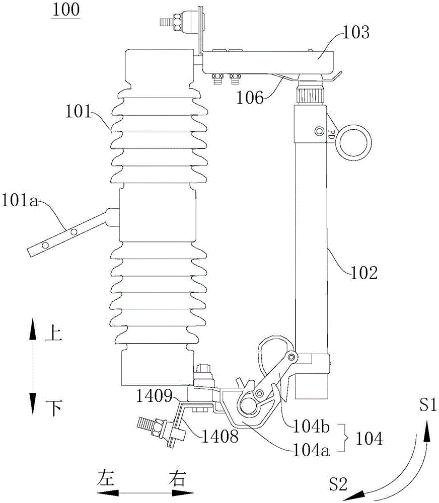
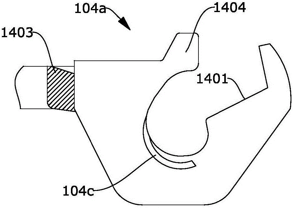
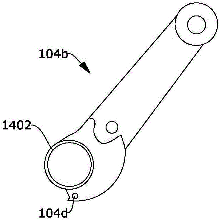
[0036] figure 1 It is a schematic structural diagram of a dropout fuse according to Embodiment 1 of the present invention; figure 2 It is a partial cross-sectional view of the first conductive seat of the dropout fuse according to Embodiment 1 of the present invention; image 3 It is a schematic structural diagram of the second conductive seat of the dropout fuse according to Embodiment 1 of the present invention. Such as Figure 1 to Figure 3 As shown, the dropout fuse 100 includes an insulator 101 . The insulator 101 is preferably a ceramic insulator or a synthetic insulator. The insulator 101 can be installed on the utility pole or other positions to be installed through the holed sheet 101a in the middle.
[0037] The dropout fuse 100 also includes a rainproof cap 103 formed by stamping a stainless steel plate. The structure of the rainproof cap 103 is a channel steel shape. A conductive member 106 with a slot is disposed inside the cap 103 . Wherein, the conductive me
Embodiment 2
[0044] Figure 4 It is the detection system and dust cleaning system of the drop-out fuse according to the second embodiment of the present invention; Figure 5 It is a circuit diagram of the detection system of the drop-out fuse according to the second embodiment of the present invention; Image 6 is a partial view of the self-adaptive air outlet in Embodiment 2; Figure 7 It is a partial view of the heat sink of the component in the second embodiment; among the figures, the meanings indicated by each reference mark are as follows; 1, the housing; 2, the PCB circuit board; 11, cleaning the air intake device; 12, the filter device; 13, Cleaning pipeline; 14. Self-adaptive air outlet; 15. Bimetal sheet; 16. Single heat sink; 17. Mirror surface; 18. Photosensitive switch; 19. Circuit components; 20. Air exhaust port; 24. Laser generator. The second embodiment is to increase the detection system and the dust cleaning system on the basis of the first embodiment.
[0045] The drop
Embodiment 3
[0067] Figure 7 It is a structural schematic diagram of the heat sink in Embodiment 3 of the present invention; in the figure, the meanings indicated by the reference signs that have appeared in the drawings used in Embodiment 2 follow the meanings in the drawings of Embodiment 2, and the newly appearing reference symbols The meanings expressed are as follows;
[0068] The difference between this embodiment and embodiment two is:
[0069] The individual heat sinks 16 are all arranged on an insulating heat conductor 23 , and the individual heat sinks 16 are divided along a circle.
[0070] The insulated heat conductor 23 can be an insulating layer attached to a metal material, so that the individual heat sinks 16 are insulated from each other without significantly reducing the thermal conductivity, so that the individual heat sinks 16 of the heat sink form a capacitor.
PUM
 Abstract
Description
Claims
Application Information
 - R&D Engineer
- R&D Manager
- IP Professional
- Industry Leading Data Capabilities
- Powerful AI technology
- Patent DNA Extraction
Browse by: Latest US Patents, China's latest patents, Technical Efficacy Thesaurus, Application Domain, Technology Topic.
© 2024 PatSnap. All rights reserved.Legal|Privacy policy|Modern Slavery Act Transparency Statement|Sitemap