Combined mold for producing electric wire rack

A technology of combining molds and wires, applied in the direction of manufacturing tools, presses, etc., can solve the problems of peeling off insulation and easy danger, and achieve the effect of rapid cooling

Inactive Publication Date: 2016-12-07
天津帅通科技发展有限公司
View PDF5 Cites 0 Cited by
  • Summary
  • Abstract
  • Description
  • Claims
  • Application Information

AI Technical Summary

Problems solved by technology

If the wires rub against each other, the insulation will fall off, and

Method used


Image

  • Combined mold for producing electric wire rack
  • Combined mold for producing electric wire rack

Examples


Embodiment Construction

[0016] It should be noted that, in the case of no conflict, the embodiments of the present invention and the features in the embodiments can be combined with each other.

[0017] In describing the present invention, it should be understood that the terms "center", "longitudinal", "transverse", "upper", "lower", "front", "rear", "left", "right", " The orientations or positional relationships indicated by "vertical", "horizontal", "top", "bottom", "inner" and "outer" are based on the orientations or positional relationships shown in the drawings, and are only for the convenience of describing the present invention and Simplified descriptions, rather than indicating or implying that the device or element referred to must have a particular orientation, be constructed and operate in a particular orientation, and thus should not be construed as limiting the invention. In addition, the terms "first", "second", etc. are used for descriptive purposes only, and should not be understood as


PUM


Abstract

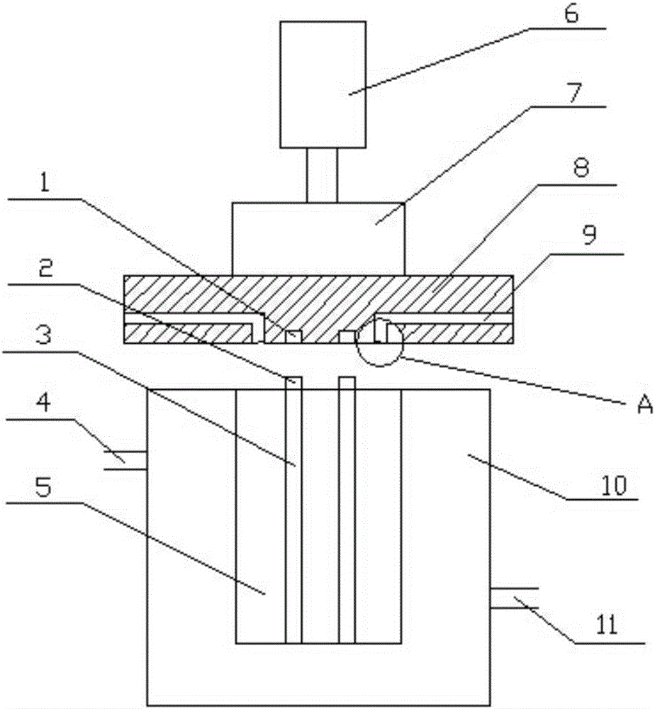
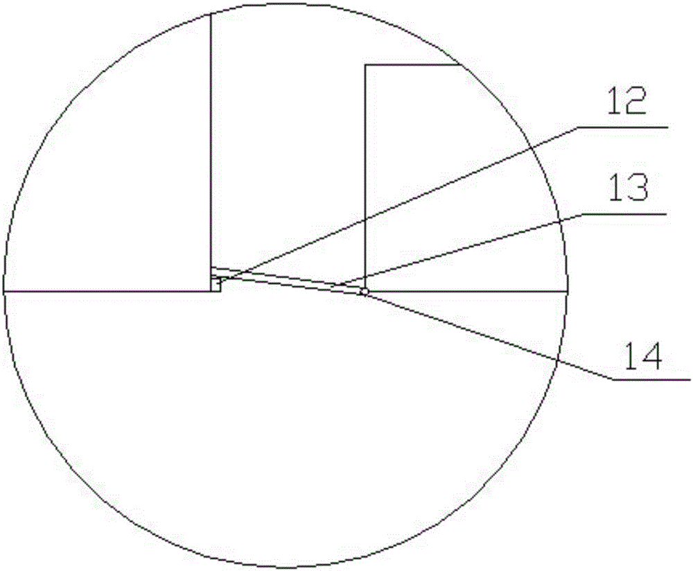
The invention discloses a combined mold for producing an electric wire rack. The combined mold for producing the electric wire rack comprises an upper mold plate, a lower mold block, a pressing block and a hydraulic cylinder. The upper mold plate and the lower mold block are in mutual spliced joint. The pressing block is fixed to the upper end of the upper mold plate. A piston rod of the hydraulic cylinder is fixed to the upper end of the pressing block. A mold cavity is formed in the middle of the lower mold block. A plurality of locating columns are fixed in the mold cavity. The height of each locating column is equal to that of the mold cavity. The upper mold plate is provided with discharging channels. One end of each discharging channel communicates with the mold cavity. The other end of each discharging channel communicates with the side face of the upper mold plate. A water flow channel is arranged in the lower mold block and surrounds the mold cavity. The outer wall of the lower mold block is provided with a water inlet and a water outlet. The combined mold for producing the electric wire rack has the advantages that the electric wire rack high in safety can be produced through cooperation, redundant waste can be conveniently discharged, and the electric wire rack can be rapidly cooled in the forming process.

Description


Claims


Application Information

Patent Timeline
Owner 天津帅通科技发展有限公司
Why Eureka
Try Eureka