Magnetic-induction liquid-level monitor based on CAN bus

A CAN bus, liquid level monitoring technology, applied in the direction of buoy liquid level indicator, etc., can solve the problems of manual observation, unexpected situations can not be handled in time, liquid level gauge can not work normally, etc., to ensure the effect of normal operation

Inactive Publication Date: 2017-01-04
TIANJIN XINCHENG INSTR & METER PLANT
View PDF11 Cites 0 Cited by
  • Summary
  • Abstract
  • Description
  • Claims
  • Application Information

AI Technical Summary

Problems solved by technology

Existing liquid level gauges are usually installed on the monitoring site, and the monitoring personnel need to conduct manual observation on site. They do not have the function of remote monitoring, cannot know the liquid level of the site equipment in real time, and ca

Method used


Image

  • Magnetic-induction liquid-level monitor based on CAN bus
  • Magnetic-induction liquid-level monitor based on CAN bus
  • Magnetic-induction liquid-level monitor based on CAN bus

Examples


Example Embodiment

[0019] Embodiments of the present invention are described in further detail below in conjunction with the accompanying drawings:

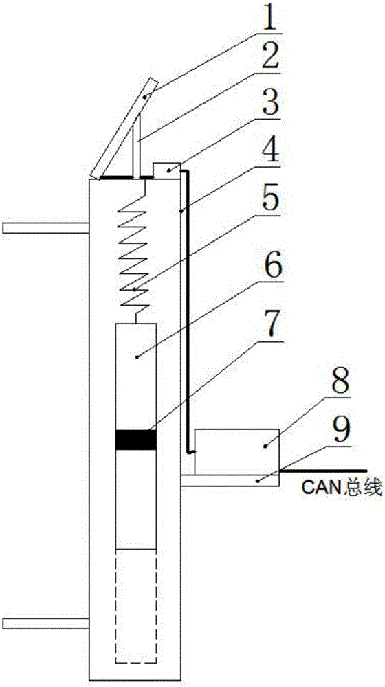
[0020] A magnetic induction liquid level monitoring device based on CAN bus, such as figure 1 As shown, it includes a cylindrical casing 4 and an electric control device 8, a spring 5 is installed on the inner wall of the top end of the cylindrical casing, a buoy 6 is installed at the bottom end of the spring, a magnetic steel 7 is installed in the buoy, and The solar panel 1 is installed on the upper surface of the cylindrical shell through the solar panel bracket 2, the solar panel is connected with the battery 3, and the output end of the battery is connected to the electric control device, and the electric control device is installed on the outer wall of the cylindrical shell. on the bracket 9 of the electronic control device.

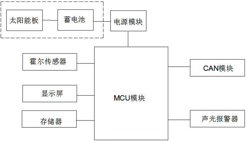
[0021] like figure 2 As shown, the electronic control device includes an MCU module, a power supply module, a Hall se


PUM


Abstract

The invention relates to a magnetic-induction liquid-level monitor based on a CAN bus. The magnetic-induction liquid-level monitor is characterized by comprising a cylindrical shell and an electronic control device, a spring is arranged on the inner wall of the top end of the cylindrical shell, a float is arranged at the bottom end of the spring, a magnet is installed in the float, and the electronic control device comprises an MCU module, a power supply module, a Hall sensor, a CAN module and an acousto-optic alarm module. The MCU module is connected with the Hall sensor and realizes the measurement of the liquid level by the magnet. The MCU module and the acousto-optic alarm module are connected to achieve the sound and light alarm function, the MCU module and the CAN module are connected to the monitoring center through the CAN bus to monitor the data transmission. The magnetic-induction liquid-level monitor detects the magnet in the float through the Hall sensor, realizes the accurate monitoring function of the liquid level, the abnormal condition alarming function, connects to the monitoring center through the CAN bus and transmits the monitoring data, and the supervisor can deal with the abnormal situation quickly and ensure the normal operation of the industrial production.

Description


Claims


Application Information

Patent Timeline
Owner TIANJIN XINCHENG INSTR & METER PLANT
Why Eureka
Try Eureka