A power winding structure

A winding structure and electric power technology, which is applied in the field of electric power, can solve problems such as inconvenient maintenance, unadjustable position, and potential safety hazards, and achieve the effects of high installation stability, improved stability, and improved safety

Inactive Publication Date: 2018-03-20
智方设计股份有限公司
View PDF6 Cites 0 Cited by
  • Summary
  • Abstract
  • Description
  • Claims
  • Application Information

AI Technical Summary

Problems solved by technology

[0002] In the process of electric power erection, it is necessary to use electric poles to support the electric wires, avoid the sagging caused by the excessive length of the electric wires, and avoid the breakage of the electric wires after drooping. When the electric wires are supported by the electric poles, they need to bypass The winding structure of the set, the winding structure in the prior art is a simple column, the bottom

Method used


Image

  • A power winding structure
  • A power winding structure
  • A power winding structure

Examples


Example Embodiment

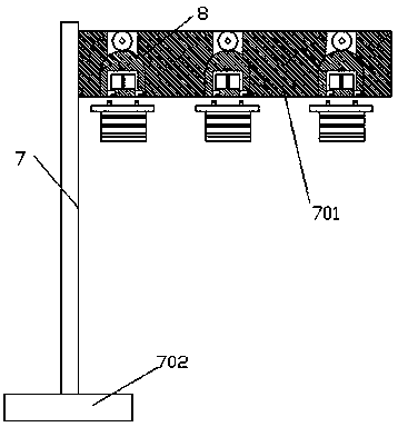
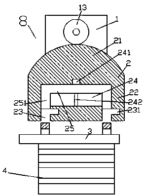
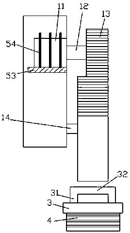
[0021] Such as Figure 1-Figure 6 As shown, an electric power winding structure of the present invention includes a utility pole 7 and a wire winder 8. The bottom of the utility pole 7 is fixed with a base 702, and the upper right end of the utility pole 7 is provided with a straight portion 701. The front end surface of the straight portion 701 is evenly provided with two or more sets of winders 8, the winders 8 including a straight plate 1, an operating part 2 connected with the straight plate 1 in a rotationally fitting manner, and a matching part connected with the operating part 2 The winding part 3 of the straight board 1 is fixedly connected to the front end face of the straight portion 701, the upper end of the front end face of the straight board 1 is provided with a regulating motor 11, and the lower end of the front end face of the straight board 1 is provided There is a bearing 14, a rotating shaft 12 is rotatably connected to the regulating motor 11, a toothed wheel 1


PUM


Abstract

The invention discloses a power winding structure, which comprises a telegraph pole and winders, wherein the bottom part of the telegraph pole is fixedly provided with a base; the upper end of the right side of the telegraph pole is provided with a flat part; the front end surface of the flat part is uniformly provided with more than two groups of winders; each winder comprises a straight plate, an operating part in rotation matched connection with the straight plate and a winding part in matched connection with the operating part; the rear end surface of the straight plate is fixedly connected with the front end surface of the flat part; the upper end of the front end surface of the straight plate is internally provided with a regulation motor; the lower end of the front end surface of the straight plate is provided with a bearing; a rotation shaft is in rotation connection onto the regulation motor; a toothed wheel is fixed on the rotation shaft; and the bearing and the operation part are in rotation matched connection. The power winding structure has the advantages that the structure is simple, the mounting is convenient, the mounting stability is high, gap adjustment is facilitated, a contact interference phenomenon between adjacent wires can be effectively prevented, and the power use safety is improved.

Description


Claims


Application Information

Patent Timeline
Owner 智方设计股份有限公司
Why Eureka
Try Eureka