Shuttle valve, hydraulic system and mechanical equipment

A technology of hydraulic system and shuttle valve, used in mechanical equipment, lift valve, valve details, etc., can solve problems such as large leakage, inability to work properly, and poor stability of shuttle valve.

Pending Publication Date: 2017-08-25
HUNAN KAIENLI HYDRAULIC MACHINERY MFG CO LTD
View PDF6 Cites 2 Cited by
  • Summary
  • Abstract
  • Description
  • Claims
  • Application Information

AI Technical Summary

Problems solved by technology

[0003] However, for shuttle valves whose leakage rate is required to be within 5 drops/Min and whose sealing performance is relatively stable, the structure commonly used in the market currently adopts the steel ball sealing structure. Due to the use of round steel balls, the p

Method used


Image

  • Shuttle valve, hydraulic system and mechanical equipment
  • Shuttle valve, hydraulic system and mechanical equipment
  • Shuttle valve, hydraulic system and mechanical equipment

Examples


Embodiment Construction

[0025] The present invention will be described in detail below in conjunction with the accompanying drawings. The description in this part is only exemplary and explanatory, and should not have any limiting effect on the protection scope of the present invention. In addition, those skilled in the art can make corresponding combinations of features in the embodiments in this document and in different embodiments according to the descriptions in this document.

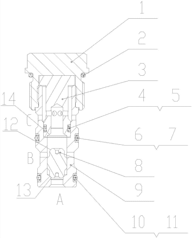
[0026] Embodiments of the present invention are as follows, see Figure 1 to Figure 3 The shown shuttle valve specifically includes a valve sleeve 9 and a valve core 8 movably arranged in the valve sleeve 9, the first end of the valve core 8, namely figure 1 The upper end shown in is provided with a first conical seat 12, and the inside of the valve sleeve 9 is also provided with a first conical seat 14 matching with the first conical seat 12, when the first conical seat 12 is matched with the first conical seat 14 At the


PUM


Abstract

The invention provides a shuttle valve. The shuttle valve comprises a valve bush and a valve element movably arranged in the valve bush. A first frustum is arranged at the first end of the valve element, a first conical base used in cooperation with the first frustum is arranged in the valve bush, and the first frustum and the first conical base are in conical surface contact. An opening A and an opening B are at least formed in the valve bush, when oil flows in the opening A, the first frustum at one end of the valve element and the first conical base are in surface contact, and conical surface seal is formed. According to the shuttle valve of the structure, one end or the two ends of the valve element are arranged to be of a frustum structure, cooperation between the valve element and the valve bush is changed into conical surface cooperation from point cooperation and linear cooperation, the sealing effect and the sealing performance of the shuttle valve are greatly improved, the sealing stability is better, it can be achieved that no leakage is generated during work, or the leakage amount is extremely small, and the requirement that the leakage speed is within 5 drops per Min is met. In addition, the invention provides a hydraulic system comprising the shuttle valve and mechanical equipment.

Description


Claims


Application Information

Patent Timeline
Owner HUNAN KAIENLI HYDRAULIC MACHINERY MFG CO LTD
Why Eureka
Try Eureka