Full-automatic welding machine

A fully automatic welding and welding device technology, applied in welding equipment, auxiliary welding equipment, welding/cutting auxiliary equipment, etc., can solve the problem of low welding efficiency, inaccurate feeding and unloading methods of tubular materials, and inability to achieve welding density precise control, etc.

Active Publication Date: 2017-11-24
安徽荣盛精密科技有限责任公司
View PDF12 Cites 11 Cited by
  • Summary
  • Abstract
  • Description
  • Claims
  • Application Information

AI Technical Summary

Benefits of technology

This patented technology describes an improved apparatus used during automated tube weldings that uses a limited range of motion to hold different parts together while they arc being worked upon by one another. It achieves this through a system called a lens or mirror box with movably mounted stops at both ends. These stop blocks prevent any movement beyond certain limits but allow it when needed. By moving these components closer towards each other, more accurate alignment can occur without having to adjust them manually. Additionally, there're also included a lift arm driven by hydraulic motors which elevation allows the equipment to work underground rather than overhead. Overall, this new design improves the accuracy and speed of tube wall weld joining processes compared to existing methods.

Problems solved by technology

This patented technical problem addressed by this patents relating to an auto welder used for joining different types of material such as pipes or tube bundles with strong metals like stainless steels (SS) without causing damage during the winding up phase when there was no longer enough pressure being applied between them.

Method used


Image

  • Full-automatic welding machine
  • Full-automatic welding machine
  • Full-automatic welding machine

Examples


Embodiment Construction

[0039] Below in conjunction with accompanying drawing and embodiment of description, specific embodiment of the present invention is described in further detail:

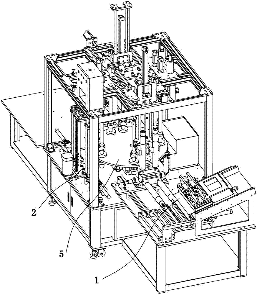
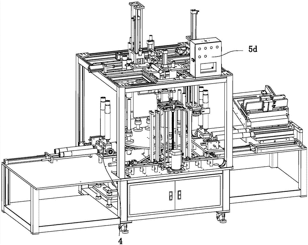
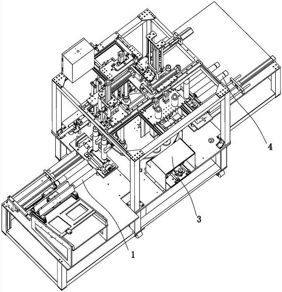
[0040] refer to Figure 1 to Figure 23 A kind of fully automatic welding machine shown, comprises feeding device 1, welding fittings feeding device 2, welding device 3, unloading device 4 and circular turntable 5, described feeding device 1, welding fittings feeding device 2. The welding device 3 and the feeding device 4 are both arranged on the side of the turntable 5, and the top edge of the turntable 5 is provided with a plurality of placement rods 5b for the materials to be sleeved. The feeding device 1 includes a feeding device 1a, an arrangement device 1b and a first rotating device 1c, the feeding device 1a includes a discharge port, the arrangement device 1b is provided with an arrangement track 1b1 matched with the discharge port, and the first rotation The device 1c is provided with a first transition bar 1c


PUM


Abstract

The invention relates to the field of welding equipment, in particular to full-automatic welding machine. The full-automatic welding machine comprises a material feeding device, a welding accessory feeding device, a welding device, a discharging device and a circular turntable, wherein the material feeding device, the welding accessory feeding device, the welding device and the discharging device are all arranged beside the turntable; a plurality of placing rods sleeved by materials are arranged at the edge of the top of the turntable; the discharging device comprises a third rotating device, and a second material conveying device which is used for transferring welded materials on the placing rods to the rotating device; the third rotating device rotates the materials from a vertical state into a horizontal state; the third rotating device comprises second transitional rods for inserting the materials; a material returning device for taking down the horizontally arranged materials on the second transitional rods is arranged beside the third rotating device; a tubular material welding mode is a double-stroke welding mode, so that the welding efficiency is improved, and the welding density is precisely controlled; and an accurate material feeding and discharging mode of tubular materials reduces the material feeding and discharging error rate.

Description


Claims


Application Information

Patent Timeline
Owner 安徽荣盛精密科技有限责任公司
Why Eureka
Try Eureka