CPU radiating device for 1U server

A technology for cooling devices and servers, which is applied in the fields of instruments, electrical digital data processing, digital data processing components, etc. The effect of accelerating heat dissipation, increasing reliability and stability, and improving heat dissipation efficiency

Inactive Publication Date: 2017-12-29
ZHENGZHOU YUNHAI INFORMATION TECH CO LTD
View PDF0 Cites 0 Cited by
  • Summary
  • Abstract
  • Description
  • Claims
  • Application Information

AI Technical Summary

Problems solved by technology

However, for 1U servers, the heat sink is limited by the height of the server itself, the height of the heat sink is low, and the heat dissipation area of

Method used


Image

  • CPU radiating device for 1U server

Examples


Embodiment Construction

[0016] The present invention will be further described below in conjunction with specific examples.

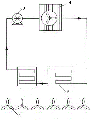
[0017] A CPU cooling device for a 1U server, including a fan 1, a CPU radiator 2, a micro hydraulic motor 3, an air-cooled radiator 4 and connecting pipes, the fan 1 is installed on one side of the CPU radiator 2, and the CPU radiator 2 Both the air-cooled radiator 4 and the air-cooled radiator 4 are provided with built-in pipelines, and the connecting pipelines connect the CPU radiator 2, the micro hydraulic motor 3 and the air-cooled radiator 4, and heat-conducting liquid is arranged in the connecting pipelines. The built-in pipes of the CPU radiator 2 and the air-cooled radiator 4 are metal pipes, and the heat transfer liquid circulation circuit is kept sealed.

[0018] When the server is running, the temperature of the CPU rises, causing the temperature of the radiator placed on the CPU to rise. Under the operation of the hydraulic motor, part of the heat is transferred to th


PUM


Abstract

The invention discloses a CPU radiating device for a 1U sever and belongs to the technical field of CPU radiating for servers. The CPU radiating device comprises a fan, a CPU radiator, a miniature hydraulic motor, an air-cooling radiator and connecting pipelines, wherein the fan is mounted on one side of the CPU radiator, each of the CPU radiator and the air-cooling radiator is provided with a built-in pipeline, the CPU radiator, the miniature hydraulic motor and the air-cooling radiator are communicated through the connecting pipeline, and a heat-conduction liquid is arranged in the connecting pipeline. The CPU radiating device has the advantages that the temperature of a CPU can be controlled to be in a certain range while energy waste is avoided, the problem that a common radiator cannot satisfy the radiating requirements of the high-power CPU on a server especially the 1U server is solved, radiating efficiency is increased, and server operation reliability and stability are increased.

Description


Claims


Application Information

Patent Timeline
Owner ZHENGZHOU YUNHAI INFORMATION TECH CO LTD
Why Eureka
Try Eureka