Efficient steel pipe cleaning device

A technology for cleaning devices and steel pipes, applied to cleaning hollow objects, cleaning methods and utensils, chemical instruments and methods, etc., can solve the problems of poor cleaning effect and low cleaning efficiency, and achieve the effect of increasing cleaning efficiency and good cleaning effect

Inactive Publication Date: 2018-01-09
上海申第实业有限公司
View PDF0 Cites 16 Cited by
  • Summary
  • Abstract
  • Description
  • Claims
  • Application Information

AI Technical Summary

Problems solved by technology

[0004] Nowadays, steel pipes are generally cleaned by direct washing wit

Method used


Image

  • Efficient steel pipe cleaning device
  • Efficient steel pipe cleaning device
  • Efficient steel pipe cleaning device

Examples


Embodiment Construction

[0026] The following will clearly and completely describe the technical solutions in the embodiments of the present invention with reference to the accompanying drawings in the embodiments of the present invention. Obviously, the described embodiments are only some, not all, embodiments of the present invention. Based on the embodiments of the present invention, all other embodiments obtained by persons of ordinary skill in the art without making creative efforts belong to the protection scope of the present invention.

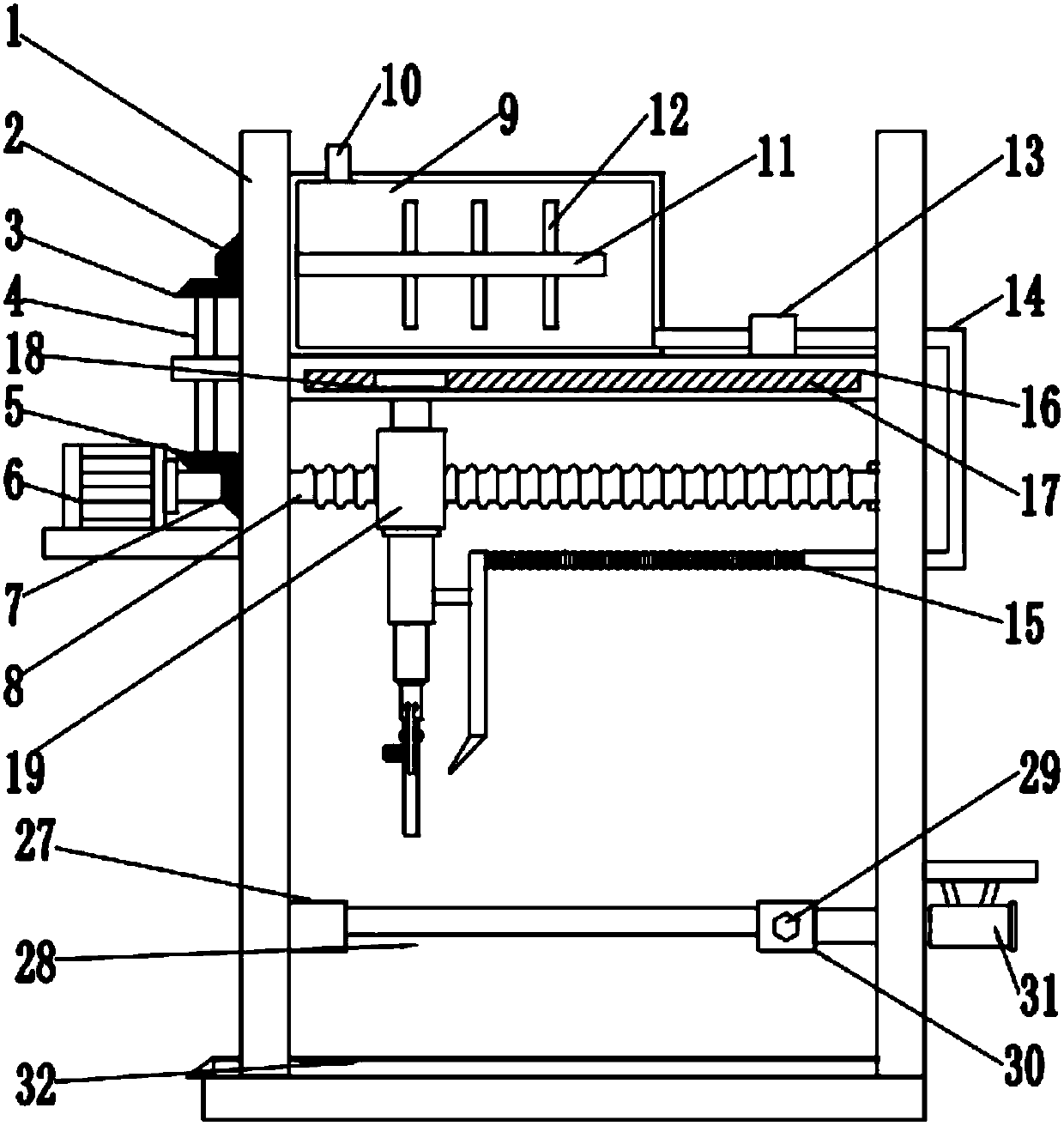
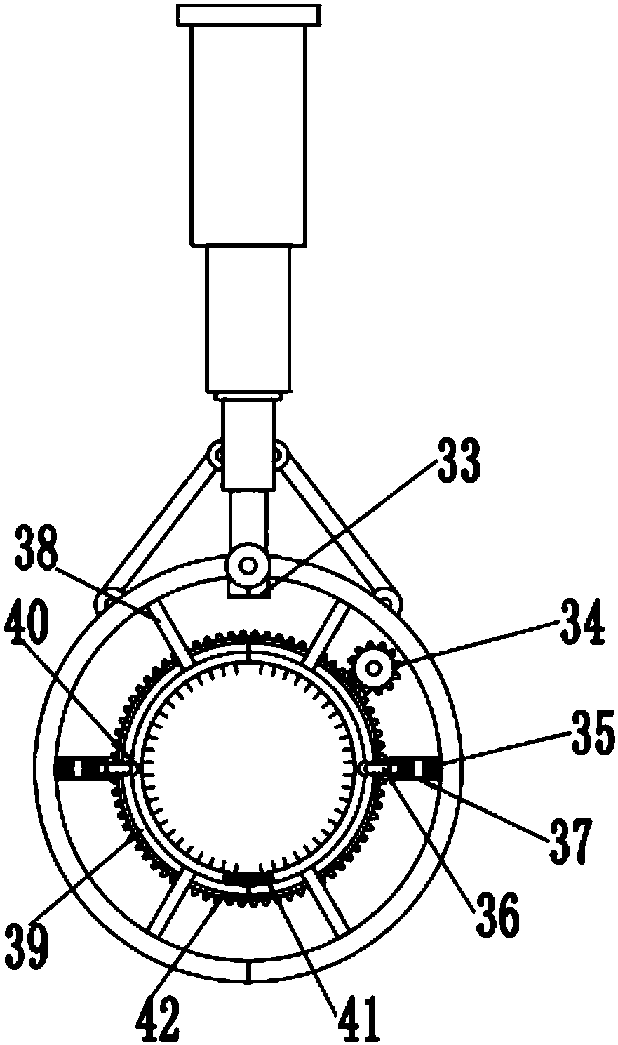
[0027] see Figure 1-7 , a high-efficiency steel pipe cleaning device, including a bracket 1, a mixing chamber 9, a support rod 16, a forward and reverse motor 6, an electric telescopic rod A20, cleaning claws, and a clamping device; the left end of the bracket 1 is provided with a forward and reverse motor 6 , the output shaft of the forward and reverse motor 6 is fixedly connected with a threaded rod 8, the threaded rod 8 runs through the left side bracket 1, a


PUM


Abstract

The invention discloses a high-efficiency steel pipe cleaning device, which includes a bracket, a mixing chamber, a support rod, a forward and reverse motor, an electric telescopic rod A, cleaning claws, and a clamping device; the left end of the bracket is provided with a forward and reverse motor, The output shaft of the rotating motor is fixedly connected with a threaded rod, the threaded rod runs through the left side bracket, and is rotatably connected with the right side bracket, the threaded rod is screwed with a fixed block; the lower end of the fixed block is fixedly connected with an electric telescopic rod A, the electric The lower end of telescopic rod A is provided with a cleaning claw, which includes electric telescopic rod B, connecting rod, rotating motor, ring claw, two-way switch, gear, electromagnet, pressing rod, sleeve, fixed rod, annular card slot, arc Groove, counterweight, semi-ring gear; a clamping device is arranged below the cleaning claw, and the clamping device is composed of symmetrically arranged placement slots A and placement slots B. The invention has the advantages of simple structure, convenient operation, increased cleaning efficiency of the steel pipe and good cleaning effect.

Description


Claims


Application Information

Patent Timeline
Owner 上海申第实业有限公司
Why Eureka
Try Eureka