Scattering device used for powder treatment and powder scattering machine

A technology of dispersing machine and powder, which is applied in the direction of grain processing, etc., can solve the problems of difficult to handle and cannot be used normally, and achieve the effects of convenient operation, efficient dispersing and efficient use.

Pending Publication Date: 2018-03-20
SHANDONG ACADEMY OF AGRI MACHINERY SCI
View PDF7 Cites 2 Cited by
  • Summary
  • Abstract
  • Description
  • Claims
  • Application Information

AI Technical Summary

Benefits of technology

This invention relates to an apparatus that uses both automation (feeders) and impact techniques to efficiently disperse particles into liquids without losing their shape or quality during processing. Its technical effect are improved efficiency and ease-of use compared with existing methods like blending them together manually by hand.

Problems solved by technology

This patented technical problem addressed by this patents relates to improving the dispersion and destruction (breakage) performance of fine particles made from materials such as calcium carbonate when they come together under strong mechanical stress that causes them clumped together after being shaken off. Current machines have issues with efficiently separating fines due to limited structure sizes and difficulties achieving efficient separation without causing excessive wear damage.

Method used


Image

  • Scattering device used for powder treatment and powder scattering machine
  • Scattering device used for powder treatment and powder scattering machine
  • Scattering device used for powder treatment and powder scattering machine

Examples


Embodiment Construction

[0024] In order to make the object, technical solution and advantages of the present invention clearer, the present invention will be further described in detail below with reference to the accompanying drawings and examples.

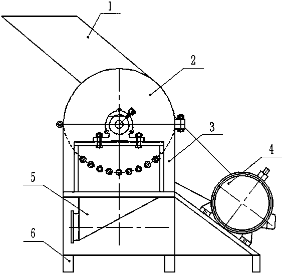
[0025] refer to figure 1 The powder dispersing machine includes a frame 6 , a dispersing device for powder processing, an input hopper 1 and an output hopper 5 .

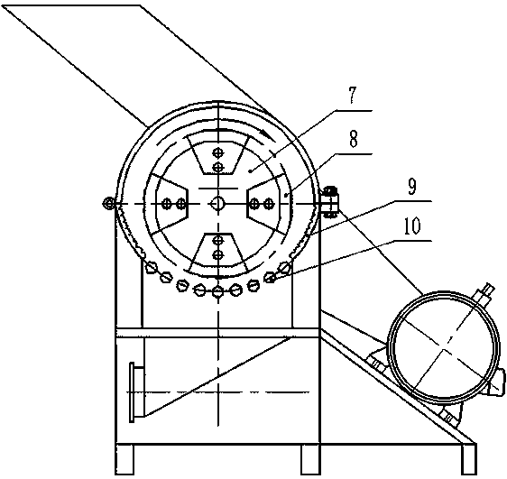
[0026] refer to figure 2 , the dispersing device used for powder processing includes a housing, a dispersing motor 4, a rotor disk 7 and

[0027] The stator part; wherein the shell is arranged on the frame 6, and the upper cavity 2 and the lower cavity 3 are installed inside the shell. One end of the upper cavity 2 and the lower cavity 3 is connected by a hinge structure, and the other end is connected by a bolt and nut assembly The detachable connection is integrated; the dispersing motor 4 is located at the side of the frame 6, and the output end of the dispersing motor 4 is connected to a


PUM


Abstract

The invention provides a scattering device used for powder treatment and a powder scattering machine. The problem about scattering of agglomerated powder, especially large agglomerated powder can be dealt with effectively, and the powder can recover to the original physicochemical property. The scattering device comprises a shell internally provided with an upper cavity and a lower cavity, a scattering motor of which the output end is connected with a rotating shaft through a transmission part, a rotor disc arranged in the shell and installed on the rotating shaft, and a stator part. One or more multifunctional plates are arranged in the rotor disc in the circumferential direction. The stator part comprises tooth plates and screen bars, wherein the tooth plates are distributed on the two sides of the lower cavity, and the screen bars are evenly distributed at the bottom of the lower cavity. The interior of the upper cavity and the interior of the lower cavity are in arc shapes, and theradius of the arc of the lower cavity is larger than the radius of the arc of the upper cavity. The rotor disc is concentric with the circle in the upper cavity, and the rotor disc, the tooth platesand the screen bars in the lower cavity form a non-concentric structure. The clearance between the outer wall of the rotor disc and the inner wall of the shell is gradually reduced from top to bottom,and therefore a gradually-changing type scattering cavity is formed.

Description


Claims


Application Information

Patent Timeline
Owner SHANDONG ACADEMY OF AGRI MACHINERY SCI
Why Eureka
Try Eureka