Direct-blowing type drying cylinder cover welded assembly

A dryer hood, direct-blowing technology, applied in textiles and papermaking, papermaking machines, dryers, etc., can solve the problems of large steam consumption, increase production costs, reduce production efficiency, etc., to improve production efficiency, The effect of reducing production costs and shortening drying time

Inactive Publication Date: 2018-04-13
SHANDONG HANTONG AOTE MACHINERY
View PDF0 Cites 0 Cited by
  • Summary
  • Abstract
  • Description
  • Claims
  • Application Information

AI Technical Summary

Benefits of technology

The technology described by this patented allows for direct contact between hot water from a device that generates it's own energy (heat) without burning any clothes or other materials being treated on them during their process. This results in faster dry times while also reducing power usage compared to traditional methods like blow-dryers.

Problems solved by technology

This patented technical problem addressed in this patents relates to improving the speed at which water can evaporate from the surface layer on top of forming sheets during printing processes without increasing their energy requirements or requiring more expensive equipment such as electricity.

Method used


Image

  • Direct-blowing type drying cylinder cover welded assembly

Examples


Embodiment Construction

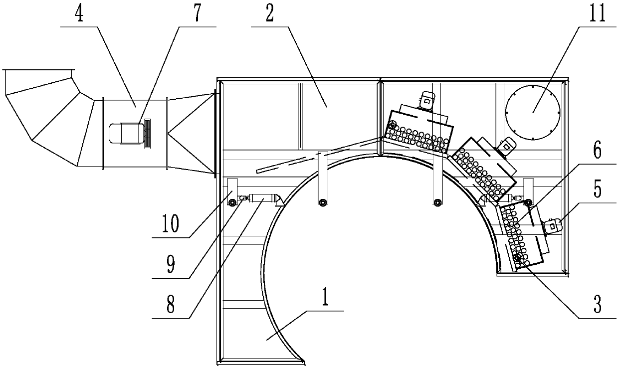
[0007] Such as figure 1 As shown, the present invention includes a main body 1, a drying cover 2, a steam inlet pipe 3, an air outlet pipe 4, a blower 5, a cooling fin 6 and an exhaust fan 7. A group of cylinders 8 are respectively installed at the left and right ends of the inner side of the top, and a group of support plates 10 are installed on the front ends of each group of cylinders 8 through the cylinder shaft 9, and the two groups of support plates 10 are welded to the drying cover 2 at the top of the main body 1 Above, the inside of the upper right end of the drying cover 2 is provided with a wet paper inlet 11, and the lower right corner of the main body 1 is provided with a steam inlet pipe 3, and the end of the steam inlet pipe 3 is connected with three sets of cooling fins along the bottom of the arc-shaped main body 1. 6. A set of blowers 5 is installed above each set of cooling fins 6 , an air outlet pipe 4 is installed outside the upper left corner of the drying co


PUM


Abstract

The invention discloses a direct-blown drying cylinder cover welding, which is characterized in that it comprises a main body, a drying cover, a steam inlet pipe, an air outlet pipe, a blower, a cooling fin and an exhaust fan, and the bottom of the main body is an inner circle Arc-shaped, a group of cylinders are respectively installed at the left and right ends of the top inside of the main body, and a group of support plates are installed on the front end of each group of cylinders through the cylinder shaft, and the two groups of support plates are welded on the drying cover at the top of the main body. Due to the adoption of the above technical scheme, the present invention has the following beneficial effects: the present invention can directly contact the high-temperature hot air generated in the heat source with the wet paper through the heat dissipation of the blower, so as to speed up the drying efficiency, shorten the drying time, and improve the production efficiency, thereby Reduce steam consumption and reduce production costs.

Description


Claims


Application Information

Patent Timeline
Owner SHANDONG HANTONG AOTE MACHINERY
Why Eureka
Try Eureka