A mold for producing cylinder liners of twin-screw extruders

A technology of twin-screw extrusion and molding machine, applied in the direction of manufacturing tools, casting molding equipment, casting mold components, etc., to achieve the effects of convenient recycling, reducing white mouth, and improving feeding efficiency

Active Publication Date: 2020-02-14
马鞍山市华威冶金机械有限公司
View PDF6 Cites 0 Cited by
  • Summary
  • Abstract
  • Description
  • Claims
  • Application Information

AI Technical Summary

Benefits of technology

This patented technical solution described in this patents describes various embodiments that improve the performance of diecast materials called double-strand ductile bars (DSRB). These dies include a spring tube system where there is nozzles inside or outside the rod head itself. By distributing coolant fluid around these features, they enhance the durability and quality of the material being poured. Additionally, the design allows for efficient processing while maintaining consistence between different parts within the injection chamber. Overall, these improvements help create stronger and more reliable products without causing issues like excessive downtime.

Problems solved by technology

This patented technology solves issues related to current methods used for manufacturing plastic products like twin syringe pumps (TSP). These include poor temperature control precision, difficulty in forming slits around the edges of the die opening, cracks formed when there're no material being cast into these openings, etc., resulting from imperfections within the injection zone itself. Additionally, previous solutions were limited because they did not address all aspects involved.

Method used


Image

  • A mold for producing cylinder liners of twin-screw extruders
  • A mold for producing cylinder liners of twin-screw extruders
  • A mold for producing cylinder liners of twin-screw extruders

Examples


Embodiment 1

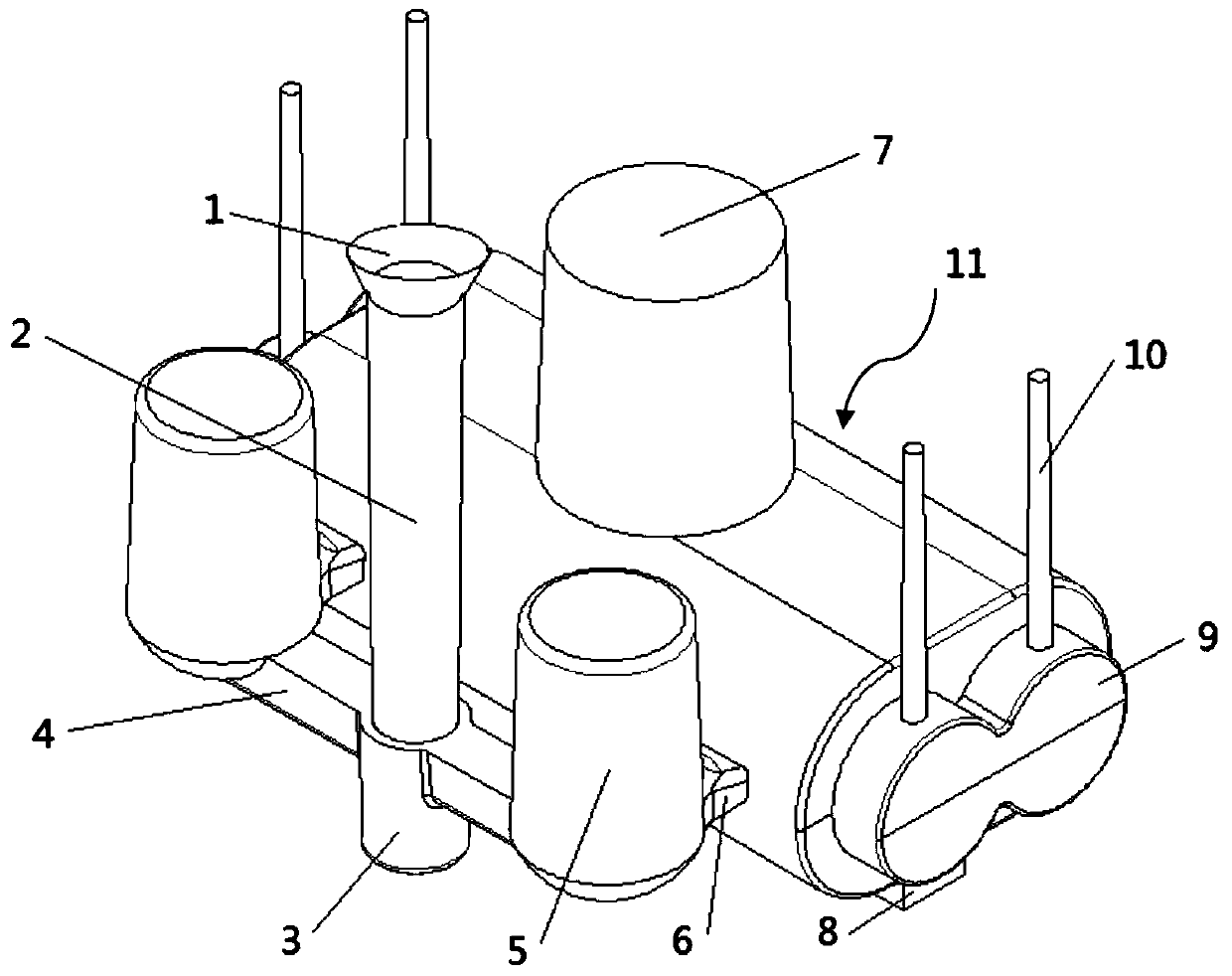
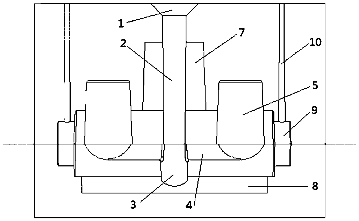
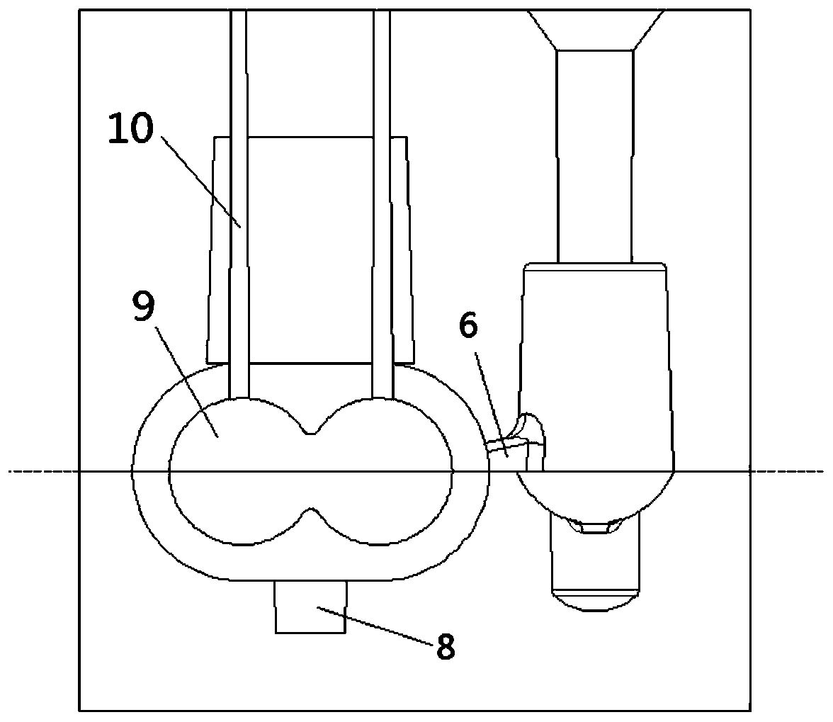
[0041] Such as figure 1 , figure 2 , image 3 , Figure 4 , Figure 5 with Image 6 As shown, a mold for producing a twin-screw extruder barrel bushing of this embodiment includes an upper box and a lower box. The upper box and the lower box enclose a twin-screw The molding cavity 11 of the barrel bushing of the extruder; the inner wall of the molding cavity 11 is ∞-shaped, and the sharp corners of the ∞-shaped junction form a thick triangular area; the middle of the molding cavity 11 is provided with a twin screw mounting hole Molded mud core 9; the top middle of the molding cavity 11 in the upper box body is provided with a heating riser 7; the bottom middle of the molding cavity 11 in the lower box body is provided with a graphite chilled iron 8; the molding cavity 11 side is close to the front and rear ends The inner gate 6 is symmetrically arranged at the part, and the outer gate 1 communicating with the inner gate 6 and a pouring channel are simultaneously arranged on the up

Embodiment 2

[0045] Such as figure 2 , image 3 , Figure 4 , Figure 5 with Image 6 As shown, the mold for producing the barrel bushing of the twin-screw extruder in this embodiment, the pouring channel is a side-mounted pouring channel, and includes a straight runner 2 and a straight runner provided in the middle of one side of the molding cavity 11. The sprue 3, the runner 4, the common riser 5 and the inner gate 6, the bottom of the sprue 2 is provided with a sprue socket 3 with an arc bottom; the upper part of the sprue socket 3 Both sides are connected to the horizontal runner 4; the ends of the two runners 4 are respectively connected with a common side riser 5; the two common side risers 5 are respectively connected with two inner gates 6; Two ingates 6 are connected with the molding cavity 11. The sprue socket 3 and the runner 4 are covered with a filter screen, and the filter screen extends into the common side riser 5 to play a filtering role.

[0046] In this embodiment, the molte

Embodiment 3

[0048] Such as figure 1 with figure 2 As shown in the present embodiment, in a mold for producing a barrel bushing of a twin-screw extruder, the sprue 2 is a vertical cylindrical hollow pipe, and the sprue 2 is located in the upper box, and The runner 2 is arranged perpendicular to the molding cavity 11, and the bottom of the sprue 2 is located on the parting surface of the upper box; the molten metal inlet end of the sprue 2 is provided with a funnel-shaped outer gate 1.

[0049] In this embodiment, the molten metal is poured from the funnel-shaped outer gate 1, passes through the sprue 2 and flows into the sprue socket 3. The funnel-shaped outer gate 1 receives the molten metal from the ladle, prevents splashing and overflow, facilitates pouring, and reduces the direct impact of the molten metal on the sprue 2;


PUM


Abstract

The invention discloses a mould for producing a double-screw plastic extruding machine barrel lining, and belongs to the field of ferrous metallurgy. The mould comprises an upper box body and a lowerbox body, a forming cavity for producing the double-screw plastic extruding machine barrel lining is defined by the upper box body and the lower box body, a mud core for forming a double-screw installation hole is arranged in the middle of the forming cavity, an exothermic riser is formed in the position, in the upper box body, of the middle of the top of the forming cavity, and graphite chill isarranged at the position, in the lower box body, of the middle of the bottom of the forming cavity; and inner gates are symmetrically formed in the positions, close to the end, of one side of the forming cavity, and an outer gate and a pouring channel which communicate with the inner gates are formed in the upper box body at the same time. According to the mould, feeding is conducted when pouringis conducted on the upper and lower thick walls of the forming cavity through the exothermic riser and the graphite chill, meanwhile heat of molten metal is dispersed by adopting the inner gates and the outer gate, the lining quality can be improved, surface cracking is reduced, and generation of a shrinkage cavity and a shrinkage porosity can be effectively prevented.

Description


Claims


Application Information

Patent Timeline
Owner 马鞍山市华威冶金机械有限公司
Why Eureka
Try Eureka