Automatic strip steel welding device

An automatic welding and strip steel technology, applied in welding equipment, welding accessories, electrode support devices, etc., can solve problems such as danger, harsh working environment, and reduced production efficiency, and achieve simple processing, low cost, and improved quality and efficiency. Effect

Pending Publication Date: 2018-05-15
HEBEI UNIV OF ENG +1
View PDF0 Cites 0 Cited by
  • Summary
  • Abstract
  • Description
  • Claims
  • Application Information

AI Technical Summary

Problems solved by technology

[0003] At present, the feeding part of the steel pipe production line is carried out by people to feed the steel coils. The cutting of the head and tail of the strip steel, and the butt welding of th

Method used


Image

  • Automatic strip steel welding device
  • Automatic strip steel welding device
  • Automatic strip steel welding device

Examples


Example Embodiment

[0021] The specific implementation of the present invention will be further described below in conjunction with the accompanying drawings

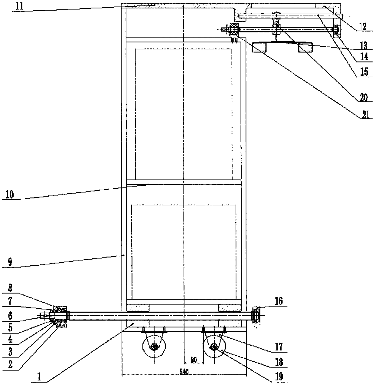
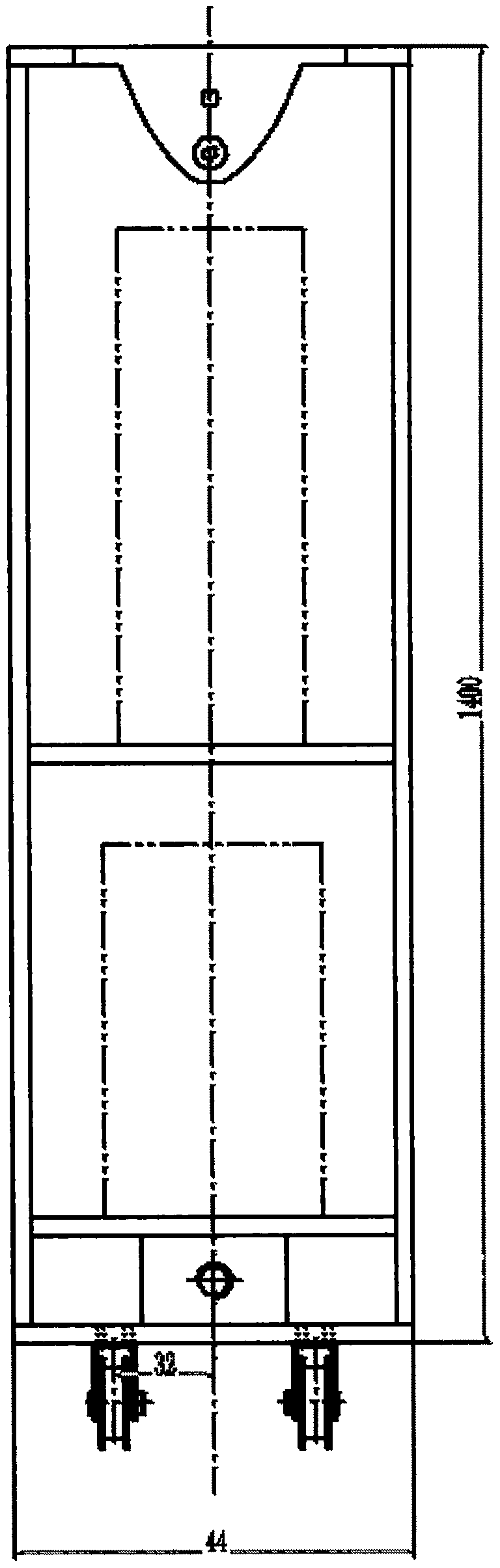
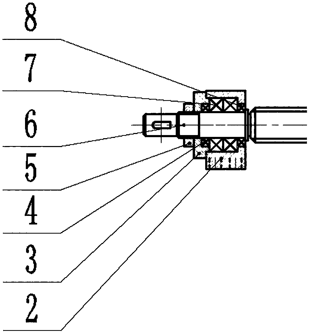
[0022] figure 1 It is a schematic diagram of the general assembly structure of the present invention. An automatic strip steel welding device proposed by the present invention is mainly composed of a main drive screw 6, a welding machine frame 9, a welding head feed screw, a bearing seat, a roller 18, a track, The bracket 12 with the guide bar, the welding head bracket 20, the control system, the welding machine system and the power system, etc. , one end of the main drive screw 6 sticks out of the head and is fixed in the bearing seat, and the other end is connected with the reduction box, the reduction box is connected with the stepper motor, and the speed and stop of the stepper motor are controlled by the control system; the welding head feeds the wire The bar passes through the bearing embedded in the upper side of the welding machine f


PUM


Abstract

The invention relates to an automatic strip steel welding device which mainly consists of a main transmission lead screw (6), a welding machine frame (9), a welding head feeding lead screw, a bearingpedestal, rollers (18), a rail, a bracket (12), a welding head bracket (20), a control system, a welding machine system and a power system; the bracket (12) is provided with a guide bar; the main transmission lead screw (6) is connected with the welding machine frame (9) through two lead screw pairs (1) inserted into the welding machine frame (9); the welding head feeding lead screw penetrates through a bearing inserted into the upper side of the welding machine frame (9); one end of the welding head feeding lead screw is fixed to the bearing pedestal at the head of the bracket (12) with the guide bar; the lead screw pairs (1) are arranged at a thread section of the welding head feeding lead screw and are used for fixing a welding head; an automatic wire feeder carries out automatic wire feeding; the welding head is arranged on the welding head feeding lead screw; a position of the welding head feeding lead screw is controlled by a proximity switch; and when welding is required, the control system controls feeding of the welding machine system and a lead screw. The welding quality and efficiency are improved, the labor intensity of a worker is reduced, and a working environment isimproved.

Description


Claims


Application Information

Patent Timeline
Owner HEBEI UNIV OF ENG
Why Eureka
Try Eureka