Duplex type oil-water separator

An oil-water separator and separator technology, which is applied in liquid separation, separation methods, chemical instruments and methods, etc., can solve the problems of low product yield, waste of resources, waste of resources, etc., so as to improve separation efficiency and avoid waste of resources. , Improve the effect of separation effect

Pending Publication Date: 2018-06-01
SHANGHAI UNIWIN PHARMA MACHINERY
View PDF0 Cites 0 Cited by
  • Summary
  • Abstract
  • Description
  • Claims
  • Application Information

AI Technical Summary

Problems solved by technology

However, some oil-water mixtures not only contain light oil that is lighter than water, but also heavy oil that is heavier than water. These heavy oils sink under the water and cannot be extracted through the discharge port on the upper part of the separator cylinder. The sewage outlet is discharged together with the magazine, resulting in waste of r

Method used


Image

  • Duplex type oil-water separator

Examples


Embodiment Construction

[0018] In order to make the technical means, creative features, goals and effects achieved by the present invention easy to understand, the present invention will be further described below in conjunction with specific illustrations.

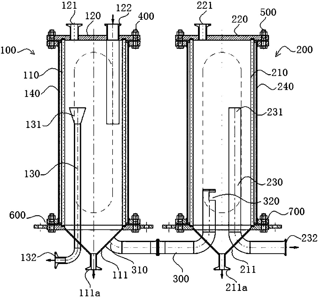
[0019] refer to figure 1 As shown, a duplex oil-water separator shown in the figure includes a first oil-water separator 100 and a second oil-water separator 200 .

[0020] The first oil-water separator 100 is used to fully separate the light oil in the oil-water mixture and to initially separate the heavy oil in the oil-water mixture. The first oil-water separator 100 includes a first separator cylinder 110. The upper end of the cylinder body 110 of the first separator is provided with a first top cover 120 , on the first top cover 120 is provided a feed port 122 , and at the bottom 111 of the first separator cylinder body 110 is provided a first heavy oil discharge port 111a.

[0021] The inside of the first separator cylinder 110 is provided wi


PUM


Abstract

The invention discloses a duplex type oil-water separator. The duplex type oil-water separator comprises a first oil-water separator and a second oil-water separator, wherein the lower part of the first oil-water separator is communicated with the lower part of the second oil-water separator through a connecting pipe; the first oil-water separator comprises a first separator cylinder, a first topcover is arranged at the upper end of the first separator cylinder, a feed port is formed in the first top cover, a first heavy oil discharge port is formed in the lower end of the first separator cylinder, a light oil collecting pipe is arranged in the first separator cylinder, an oil inlet of the light oil collecting pipe is formed in the upper part of the first separator cylinder, and an oil outlet of the light oil collecting pipe extends out from the bottom of the first separator cylinder and is communicated with a light oil collecting device. According to the duplex type oil-water separator, not only can light oil in an oil-water mixture be separated sufficiently, but also heavy oil in the oil-water mixture can be separated sufficiently, resource waste can be avoided, and environmental protection is facilitated.

Description


Claims


Application Information

Patent Timeline
Owner SHANGHAI UNIWIN PHARMA MACHINERY
Why Eureka
Try Eureka