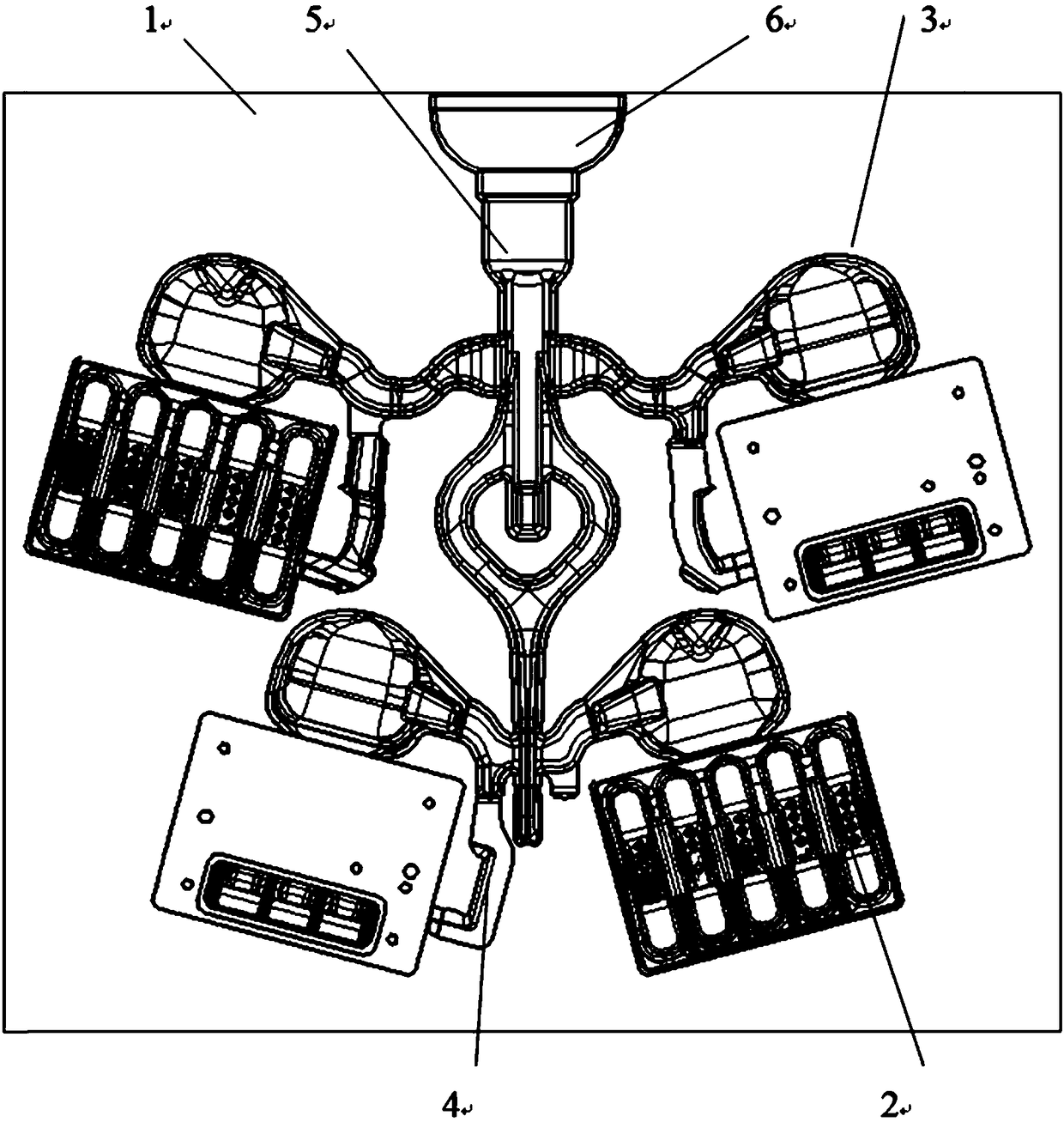
Bearing cap sand mold structure

A bearing cap and sand mold technology, applied in the direction of casting mold, core, casting mold composition, etc., can solve the problems of shrinkage porosity of castings and waste of production labor costs of the company, so as to reduce the scrap rate, reduce the risk of sand washing, and improve the The effect of process yield

Pending Publication Date: 2018-06-15
上海圣德曼铸造海安有限公司
View PDF0 Cites 0 Cited by
  • Summary
  • Abstract
  • Description
  • Claims
  • Application Information

AI Technical Summary

Benefits of technology

This technology improves the efficiency of producing castings while reducing defects caused during production processes due to excessive cooling or other factors affecting the quality of the final product. By positioned between these different locations within an inclined plane, there are fewer risers for better heat transfer from inside the metal shell towards outside airflow. Additionally, this design allows more precise control over how well it cools down after being poured into its cavities without causing any issues like getting trapped water behind them when they come out too much.

Problems solved by technology

This patented technical problem addressed in this patents relates to reducing wastage during production processes due to excessive use of bearings with conventional methods like vertical placements or horizontally placed platforms.

Method used


Image

  • Bearing cap sand mold structure

Examples


Embodiment Construction

[0014] The implementation of the present invention will be illustrated by specific specific examples below, and those skilled in the art can easily understand other advantages and effects of the present invention from the contents disclosed in this specification.

[0015] The structures, proportions, sizes, etc. shown in the drawings attached to this specification are only used to match the content disclosed in the specification for the understanding and reading of those who are familiar with this technology, and are not used to limit the conditions for the implementation of the present invention , so it has no technical substantive meaning, and any modification of structure, change of proportional relationship or adjustment of size shall still fall within the scope of the disclosure of the present invention without affecting the functions and objectives of the present invention. The technical content must be within the scope covered. At the same time, terms such as "upper", "low


PUM

PropertyMeasurementUnit
Modulusaaaaaaaaaa
Modulusaaaaaaaaaa

Abstract

The invention provides a bearing cap sand mold structure, which includes a sand mold main body, which is provided with four casting cavities that are inclinedly arranged in two groups. Each casting cavity is connected to a riser and an ingate, the risers are in top casting connected, and the ingate communicates with a sprue, which is connected to a sprue cup. In the sand mold structure, each sandmold main body is provided with a riser. In the precondition that risers are adopted as less as possible, the requirement of interior shrinkage porosity of a casting is met, and the technical yield rises. The cavities are directly connected to the ingate, so that the sand washing risk is reduced, the rejection rate is reduced, and the production efficiency is improved.

Description


Claims


Application Information

Patent Timeline
Owner 上海圣德曼铸造海安有限公司
Why Eureka
Try Eureka