Electrochromic device and application thereof
A technology of electrochromic devices and displays, applied in instruments, vehicle parts, optical observation devices, etc., can solve the problems of decreased conductivity, easy fracture, limited resources, etc., and achieve high yield rate, strong controllability, coloring high efficiency effect
- Summary
- Abstract
- Description
- Claims
- Application Information
AI Technical Summary
Problems solved by technology
Method used
Image

Examples
Example Embodiment
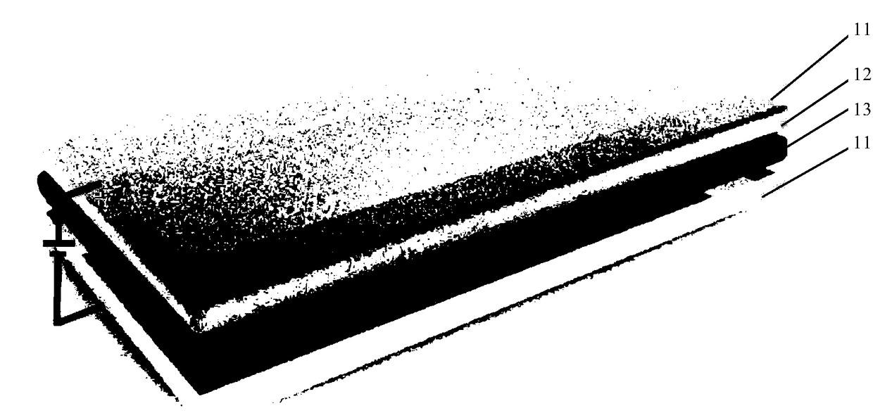
[0029] Example 1: Transmissive electrochromic device
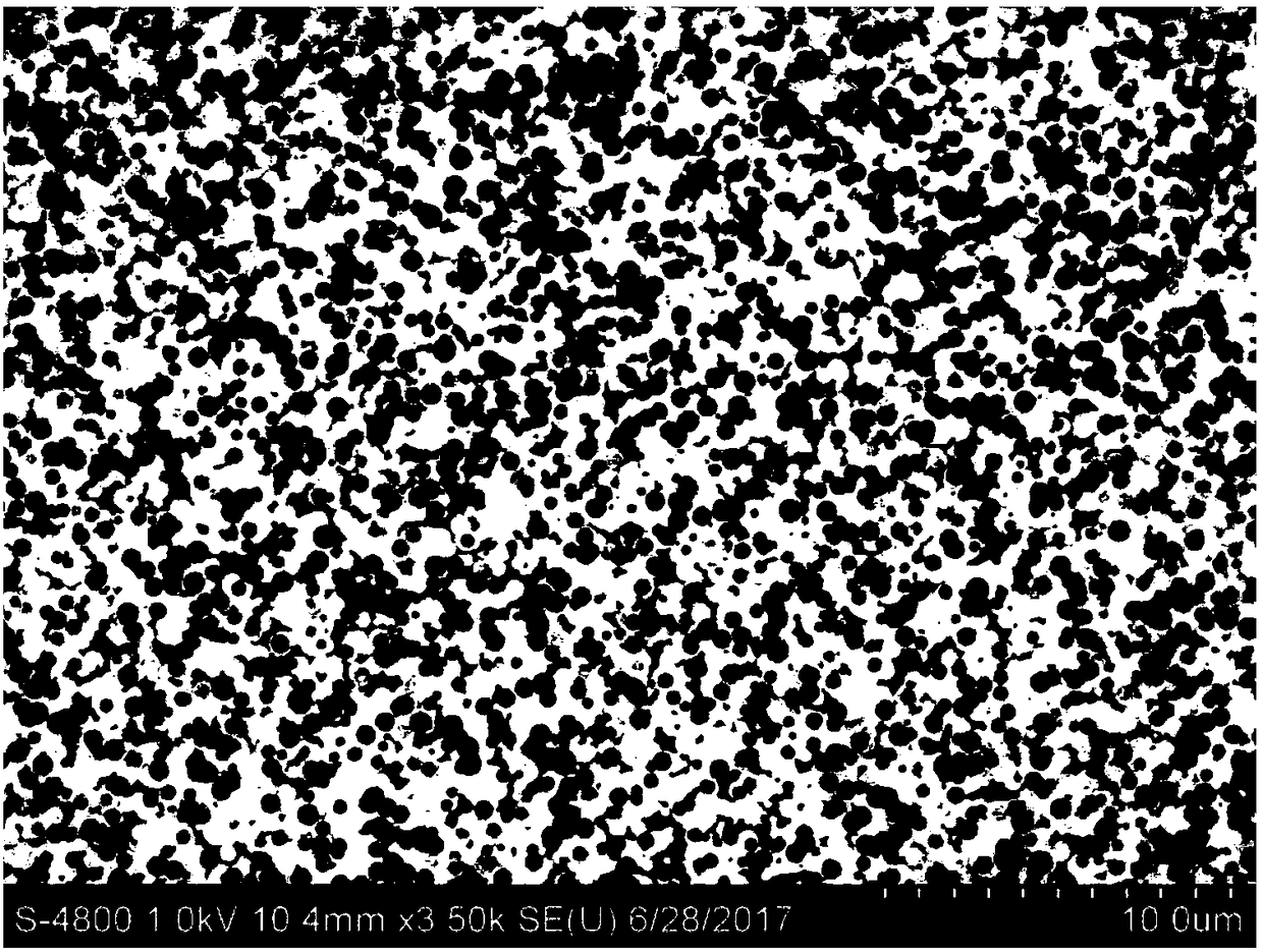
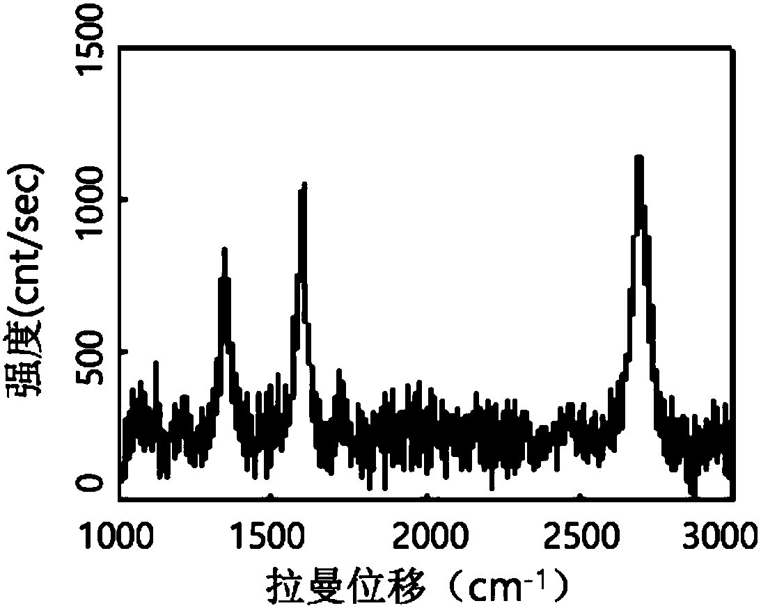
[0030] Preparation of graphene glass 11: Put the quartz glass substrate obtained after cleaning into a tube furnace, pump the pressure of the reaction chamber below 10 Pa, then pass in 500sccm of argon and 500sccm of hydrogen, and raise the temperature to 1040℃; wait for 10min to stabilize After that, 500 sccm ethanol vapor was passed into the cavity, the pressure of the reaction cavity was controlled to 1200 Pa; the growth time was 30 minutes, and chemical vapor deposition was performed. After the growth, stop passing ethanol and lower the temperature; when the temperature drops to room temperature, stop the supply of argon and hydrogen, and take out the graphene glass sample. Among them, the characterization of graphene glass SEM and Raman spectroscopy such as figure 2 , image 3 Shown. It can be seen that the graphene glass has good crystallinity and high uniformity.
[0031] Preparation of gel electrolyte: Weigh 1g of polyc
Example Embodiment
[0034] Example 2: Transmissive electrochromic device
[0035] Preparation of graphene glass 22: Put the quartz glass substrate obtained after cleaning into a tube furnace, then pass 200sccm argon and 100sccm hydrogen, and heat up to 1040°C; after stabilizing for 10min, pass 20sccm methane into the cavity. The growth time is 2h, and chemical vapor deposition is performed. After the growth, stop feeding methane and lower the temperature; when the temperature drops to room temperature, stop the supply of argon and hydrogen, and take out the graphene glass sample.
[0036] Electrolyte preparation: Add 5g propylene carbonate (PC), 1g polymethyl methacrylate (PMMA), 0.5g lithium perchlorate (LiClO) to 20g acetonitrile solution 4 ), the mixed solution is heated and stirred to dissolve to obtain a transparent gel electrolyte.
[0037] Preparation of electrochromic material: add appropriate amount of tungsten powder to the mixture of excess hydrogen peroxide and ethanol (volume ratio 1:1), reac
Example Embodiment
[0040] Example 3: Reflective electrochromic device
[0041] Preparation of graphene glass 31: Put the ordinary white glass substrate obtained after cleaning into the graphite crucible and put it into the APCVD chamber, set the Ar gas flowmeter to 500sccm, open the Ar valve, and carry out the scrubbing process, the purpose is to drive off the reaction The air in the cavity lasts for 10 minutes. After the gas cleaning is completed, the pressure of the APCVD chamber is one atmosphere, and the temperature is raised. The white glass substrate is heated to 1000°C, and Ar and H are set during the heating process 2 The flow rates are 150 sccm and 30 sccm, respectively. After the furnace temperature rises to 1000°C, it is stabilized for 20 minutes. The purpose is to stabilize the furnace temperature while annealing the sample. At this time, the white glass is liquefied into a liquid state and protected by the graphite crucible will not overflow. Set the flow rate of methane to 8 sccm. The
PUM
 Abstract
Description
Claims
Application Information
 - R&D Engineer
- R&D Manager
- IP Professional
- Industry Leading Data Capabilities
- Powerful AI technology
- Patent DNA Extraction
Browse by: Latest US Patents, China's latest patents, Technical Efficacy Thesaurus, Application Domain, Technology Topic.
© 2024 PatSnap. All rights reserved.Legal|Privacy policy|Modern Slavery Act Transparency Statement|Sitemap