Printing and dyeing raw material mixing device

A technology for mixing devices and raw materials, which is applied in mixers, mixers with rotary mixing devices, transportation and packaging, etc., can solve the problems of single function, easy to appear dirty, poor mixing effect of printing and dyeing raw materials, etc., and achieve huge economic benefits. , the effect of broad market prospects

Inactive Publication Date: 2018-10-23
ZHEJIANG XINGFEIER TECH CO LTD
View PDF0 Cites 5 Cited by
  • Summary
  • Abstract
  • Description
  • Claims
  • Application Information

AI Technical Summary

Benefits of technology

This new technology allows for better control over how much material mixes during production than previous methods like manual labor or mechanical devices alone. It uses an apparatus called a heating tank that helps keep it warm while adding different types of chemicals together. By moving back-and forth along its length, this process makes sure everything stays evenly mixed throughout without any issues such as clumpings. Additionally, there're also certain features added inside the chamber where these machines work smoothly. Overall, this innovation improves productivity efficiency and quality.

Problems solved by technology

This patented technical problem addressed in this patents relates to improving the efficiency at which we mix different types of liquid substances during printing processes such as lithography with various colors. Current methods involve adding separate components like pumps and filters beforehand, but these can be difficult to maintain due to their small size. There needs an improved solution where both the mixture process itself (the type) and its equipment work together effectively while being able to efficiently clean it from any contamination issues caused by previous usage.

Method used


Image

  • Printing and dyeing raw material mixing device
  • Printing and dyeing raw material mixing device
  • Printing and dyeing raw material mixing device

Examples


Embodiment Construction

[0020] The following will clearly and completely describe the technical solutions in the embodiments of the present invention with reference to the accompanying drawings in the embodiments of the present invention. Obviously, the described embodiments are only some, not all, embodiments of the present invention. Based on the embodiments of the present invention, all other embodiments obtained by persons of ordinary skill in the art without making creative efforts belong to the protection scope of the present invention.

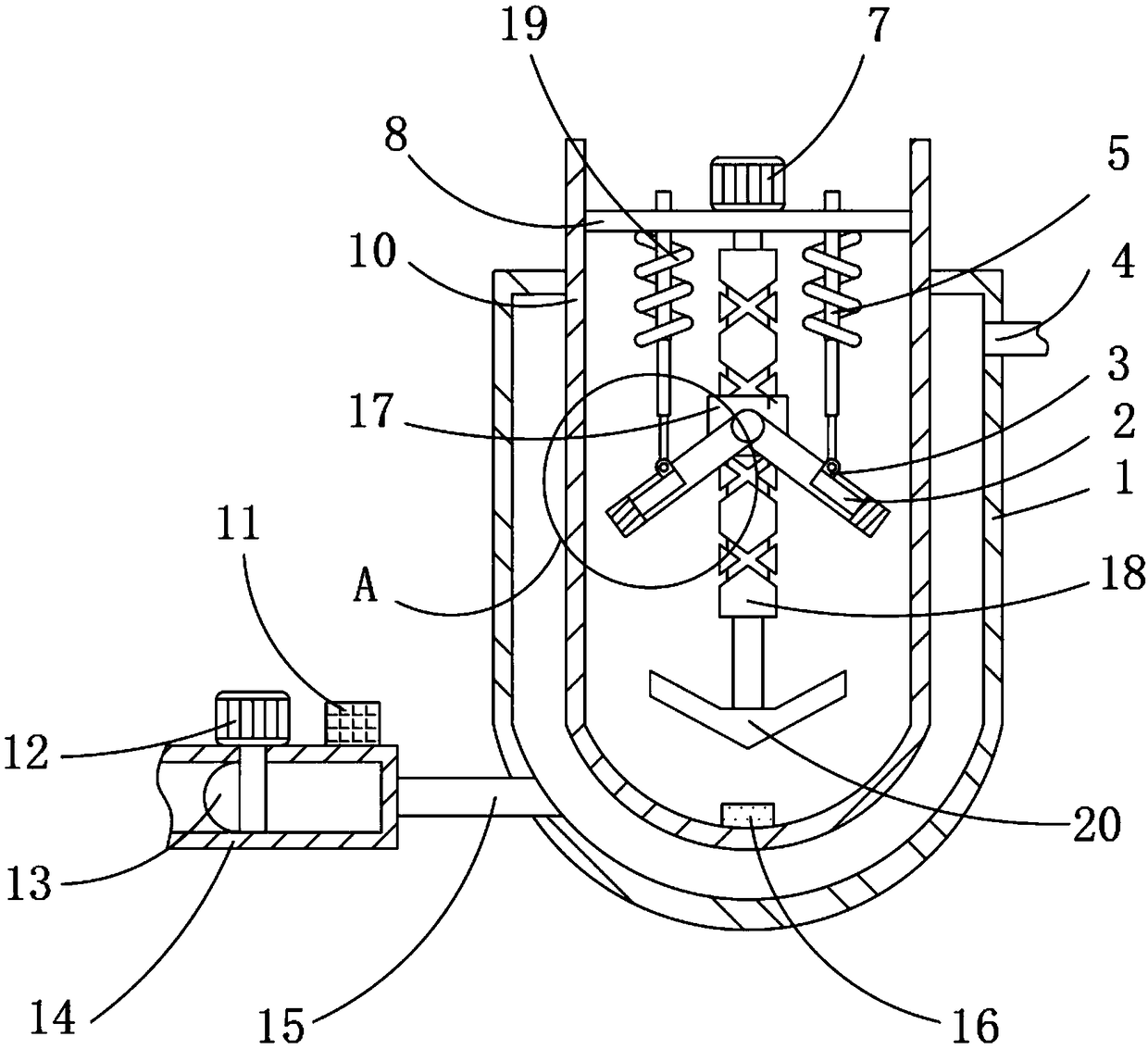
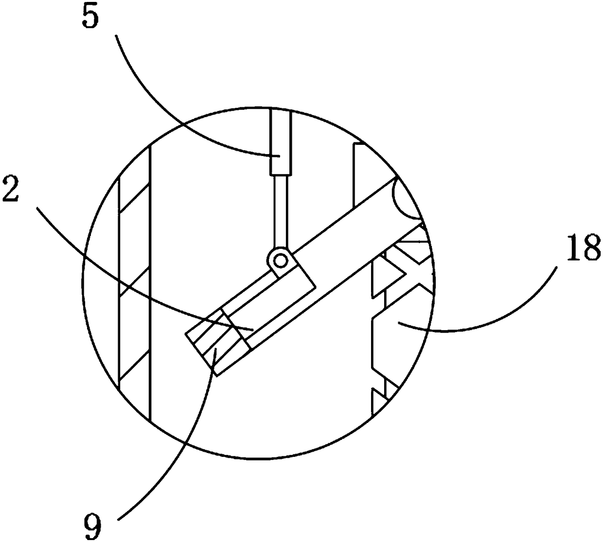
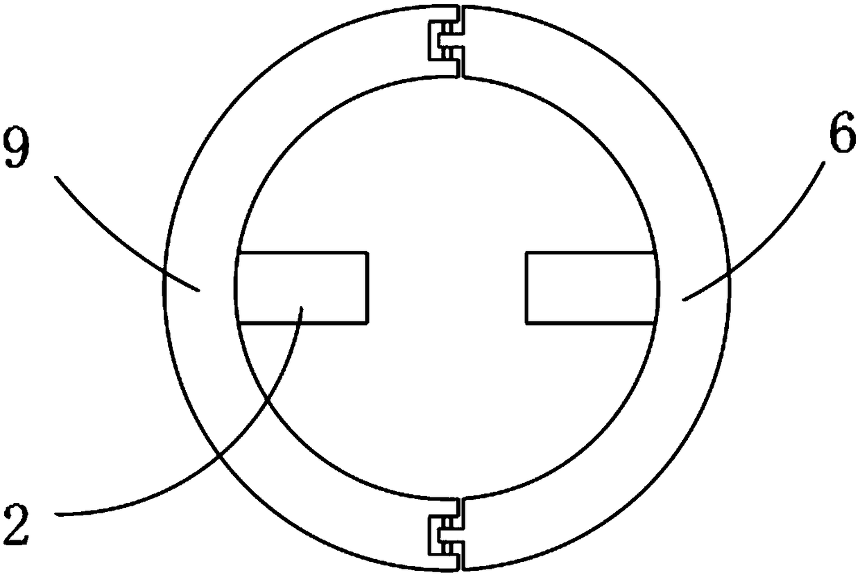
[0021] see Figure 1-3 , the present invention provides a technical solution:

[0022] A raw material mixing device for printing and dyeing, comprising a heating box 1, a water inlet pipe 15 is fixedly connected to the inside of the left end of the heating box 1, and a transition box 14 is fixedly connected to the left end of the water inlet pipe 15, and the top of the transition box 14 is on the right A CoolDrive A8 servo controller 11 is fixedly connected to t


PUM


Abstract

The invention relates to the technical field of printing and dyeing raw material mixing, in particular to a printing and dyeing raw material mixing device which comprises a heating box. A water inletpipe is fixedly connected on the left inner side of the heating box, a transition box is fixedly connected at the left end of the water inlet pipe, a CoolDrive A8 servo controller is fixedly connectedon the right of the top end of the transition box, the a 1FK7083-5AF1-1DG2 servo motor is fixedly connected at the top end of the transition box, a plug is fixedly connected at the left end of a spindle of the 1FK7083-5AF1-1DG2 servo motor, and a horizontal disk is fixedly connected on the inner side of the top end of a mixing box. The mixing device is provided with a first cleaning ring, an electric telescopic rod and a spring. The position between the first cleaning ring and the second cleaning ring is adjusted, on one hand, raw materials can be vertically stirred by the first cleaning ringand a second cleaning ring, on the other hand, the inner wall of the mixing box can be cleaned through the action of the first cleaning ring and the second cleaning ring, and the printing and dyeingraw material mixing device has huge economic benefits and wide market prospects and is worthy of popularization and use.

Description


Claims


Application Information

Patent Timeline
Owner ZHEJIANG XINGFEIER TECH CO LTD
Why Eureka
Try Eureka