Grinding assembly and waste processor
A component and cutter head technology, applied in the field of grinding components and garbage disposals, can solve the problems of affecting the grinding effect, damaging the grinding components, and difficult to ensure the parallelism of the mounting parts, so as to improve the grinding efficiency, speed up the discharge speed, and improve the grinding effect. Effect
- Summary
- Abstract
- Description
- Claims
- Application Information
AI Technical Summary
Benefits of technology
Problems solved by technology
Method used
Image

Examples
Embodiment 1
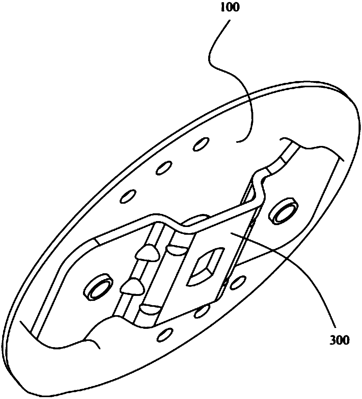
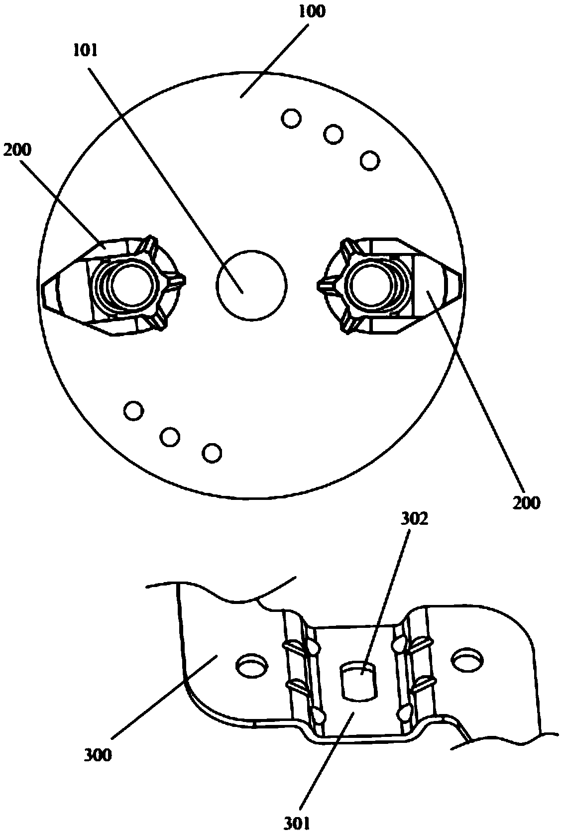
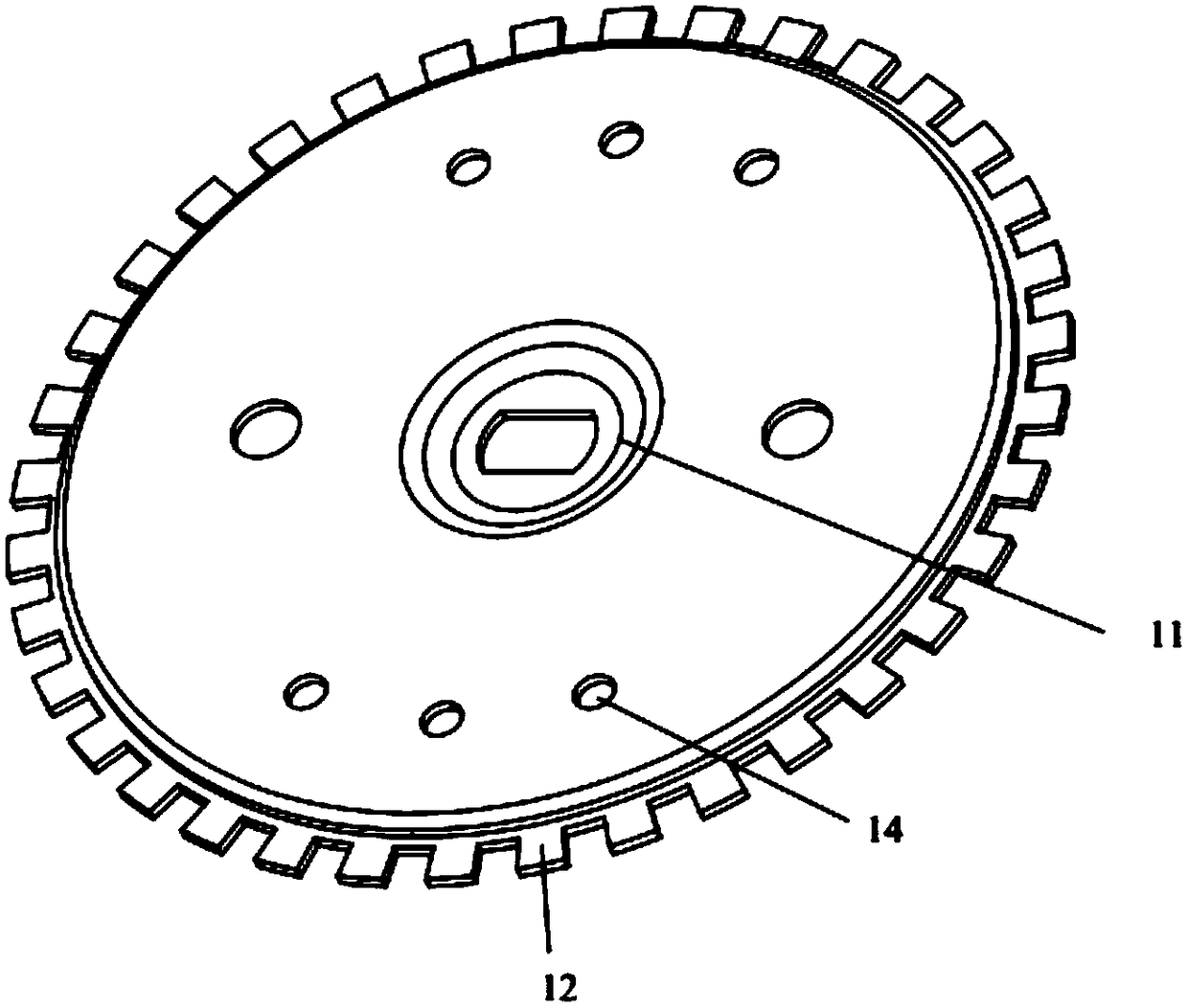
[0055] Such as Figure 3-6 As shown, the grinding assembly provided in this embodiment includes a cutterhead 1, a bolt 2, and a grinding hammer 3 installed on the cutterhead 1. The grinding hammer 3 can rotate relative to the cutterhead 1, wherein the center of the cutterhead 1 is set There is a first groove 11, and a through hole is provided in the center of the first groove 11, the bolt 2 includes a nut 21 and a screw rod 23 fixedly connected, the screw rod 23 passes through the through hole and is used to drive the cutter head 1 to rotate The installation shaft is connected to lock and fix the cutterhead 1 on the installation shaft; in this embodiment, the installation shaft is the output shaft of the motor, and the output shaft is provided with a screw hole, so the screw 23 is connected with the screw hole that is provided on the described mounting shaft. In addition, the through hole opened in the center of the first groove 11 is preferably a waist-shaped hole, which is con
Embodiment 2
[0066] Such as Figure 7 As shown, the difference between the grinding assembly provided in this embodiment and the grinding assembly in Embodiment 1 lies in the cutterhead 1. No working teeth 12 are added to the cutterhead 1 provided in this embodiment, and the rest of the structures are the same, and will not be repeated here. repeat. In some occasions, when the food waste does not need to be ground to a very fine level, for example, the grinding level is relatively low, the cutterhead 1 in this embodiment can be used to grind the food waste.
Embodiment 3
[0068] Such as Figure 8-9As shown, the difference between the grinding assembly provided in this embodiment and the grinding assembly in Embodiment 2 is that the cutter head 1 provided in this embodiment is provided with a second groove 13, and the second groove 13 is formed by the first groove 11 Centered along the circumferential direction of the cutter head 1, the second groove 13 can be used to temporarily store ground food waste, thereby preventing excessive food waste from accumulating between the edge of the cutter head 1 and the fixed knife 4 position to avoid jamming during the grinding process. Specifically, the groove surface of the second groove 13 is an arc surface, and the opening of the second groove 13 expands outwards, so that the garbage is separated from the second groove 13, preventing the garbage from accumulating in the second groove for a long time. Within 13, it affects the grinding effect.
[0069] Optionally, the second grooves 13 are arranged along t
PUM
| Property | Measurement | Unit |
|---|---|---|
| Diameter | aaaaa | aaaaa |
| Diameter | aaaaa | aaaaa |
| Diameter | aaaaa | aaaaa |
Abstract
Description
Claims
Application Information
 - R&D Engineer
- R&D Manager
- IP Professional
- Industry Leading Data Capabilities
- Powerful AI technology
- Patent DNA Extraction
Browse by: Latest US Patents, China's latest patents, Technical Efficacy Thesaurus, Application Domain, Technology Topic.
© 2024 PatSnap. All rights reserved.Legal|Privacy policy|Modern Slavery Act Transparency Statement|Sitemap