Composite microsphere with radial fibrous mesoporous shell layer/hollow nuclear layer structure and preparation method of composite microsphere

A composite microsphere and fibrous technology, which is applied in the preparation of microspheres and microcapsule preparations, can solve the problems of serious agglomeration of hollow microspheres, limit the application of hollow microspheres, and harsh synthesis conditions, and achieve adjustable performance, Ease of industrial production and improved performance of microspheres

Active Publication Date: 2019-04-19
ETERNAL SPECIALTY MATERIALS ZHUHAI CO LTD
View PDF11 Cites 4 Cited by
  • Summary
  • Abstract
  • Description
  • Claims
  • Application Information

AI Technical Summary

Benefits of technology

This patented technology improves upon previous methods by providing a new type of material called honeycomb microparticles that have unique shapes like those found on regular particles or flakes. These special structures help scatter lights more effectively than traditional ones while maintaining their original appearance. They may find use in applications where they improve opacification (the ability to hide imperfections) without adding bulkiness or thickness.

Problems solved by technology

This patented technical problem addressed in this patents relates to finding ways to improve the efficiency and performance of porous silicon structures used in various applications like solar cells due to their unique features that include small sizes, stable surfaces, continuous tunability over different wavelength ranges, and potential use within certain fields. Previous attempts at solving these issues were limited successively, complicated procedures requiring expensive equipment, long reaction times, poorly dispersible powders, and potentially dangerous chemical reagents.

Method used


Image

  • Composite microsphere with radial fibrous mesoporous shell layer/hollow nuclear layer structure and preparation method of composite microsphere
  • Composite microsphere with radial fibrous mesoporous shell layer/hollow nuclear layer structure and preparation method of composite microsphere
  • Composite microsphere with radial fibrous mesoporous shell layer/hollow nuclear layer structure and preparation method of composite microsphere

Examples


Embodiment 1

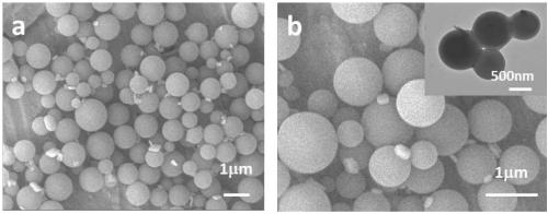
[0092] Add 6 g of styrene monomer to a three-necked flask filled with 100 mL of deionized water, stir mechanically at room temperature (250 rpm), and pass nitrogen gas for 30 min. When the temperature was raised to 70°C under a nitrogen atmosphere, 60mg of initiator KPS was added and reacted for 24h. The product was transferred to a centrifuge tube, centrifuged, washed with ethanol, centrifuged, and dried in a blast oven at 50°C for use. The product looks like figure 1 As shown, the average particle size is 967nm, and the polydispersity index (PDI) is 1.11.

[0093] Weigh 0.4g of cetyltrimethylammonium bromide (CTAB) into a 100mL round bottom flask, then add 20mL of water and 8mL of absolute ethanol into the flask. Weigh 450 mg of the prepared polystyrene microspheres into the flask, then add 1 mL of ammonia water, and stir at room temperature for 30 min. Add 500 μL TEOS dropwise to the system, and react at room temperature for 24 h under stirring conditions.

[0094] Subsequ

Embodiment 2

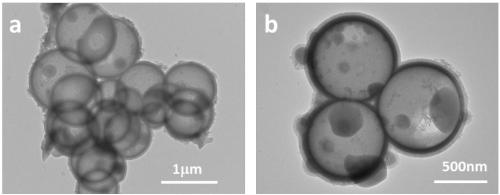
[0097] Prepare the composite microsphere with radial fibrous mesoporous shell / hollow core layer structure in the same manner as in Example 1, the difference is that the first polymerization reaction time for preparing the hollow core layer is 12 hours, and the prepared TEM photos of composite microspheres with radial fibrous mesoporous shell / hollow core structure see Image 6 , Figure 7 for Image 6 - Enlarged view of the composite microspheres in b, the average particle size of the corresponding composite microspheres is 1 μm.

Embodiment 3

[0099] Composite microspheres with a radial fibrous mesoporous shell / hollow core structure were prepared in the same manner as in Example 1, except that the organic solvent was replaced by n-hexane.


PUM

PropertyMeasurementUnit
The average particle sizeaaaaaaaaaa
Thicknessaaaaaaaaaa
Specific surface areaaaaaaaaaaa

Abstract

The invention relates to a composite microsphere with a radial fibrous mesoporous shell layer/hollow nuclear layer structure and a preparation method of the composite microsphere. The composite microsphere is provided with a cavity, a nuclear layer and a mesoporous shell layer, wherein the mesoporous shell layer is provided with radial fibrous mesoporous channels. The composite microsphere is highin sphericity and surface regularity, uniform in particle size distribution and high in monodispersity and strength. The preparation method of the composite microsphere is simple and feasible and facilitates industrialization; preparation of the radial fibrous mesoporous shell layer and removal of an organic template can be completed by means of a one-step method. The composite microsphere has the advantages of high light scattering efficiency, large specific surface area, low density, high porosity and the like, can be widely applied in light diffusion materials and used as a light diffusionagent for heavy haze and can also be adopted in the fields of fillers of coatings, cosmetics, catalysts and water treatment.

Description


Claims


Application Information

Patent Timeline
Owner ETERNAL SPECIALTY MATERIALS ZHUHAI CO LTD
Why Eureka
Try Eureka