Phase change heat storage device

A phase-change heat storage and hot water technology, which is applied in heat storage equipment, heat storage heaters, fluid heaters, etc., can solve the problems of insignificant enhancement of heat transfer effect, heavy material weight, stratification or settlement, etc. Light weight, good heat storage performance and low supercooling

Inactive Publication Date: 2019-04-19
SOUTHEAST UNIV
View PDF12 Cites 10 Cited by
  • Summary
  • Abstract
  • Description
  • Claims
  • Application Information

AI Technical Summary

Problems solved by technology

However, filling these existing thermally conductive materials has problems such as relatively low thermal conductivity, no obvious enhancement of heat transfer effect, heavy material weight, and metal powder delamination or sedimentation in phase change materials.

Method used


Image

  • Phase change heat storage device
  • Phase change heat storage device

Examples


Example Embodiment

[0020] The technical solution of the present invention will be further described below in conjunction with the drawings and specific embodiments.

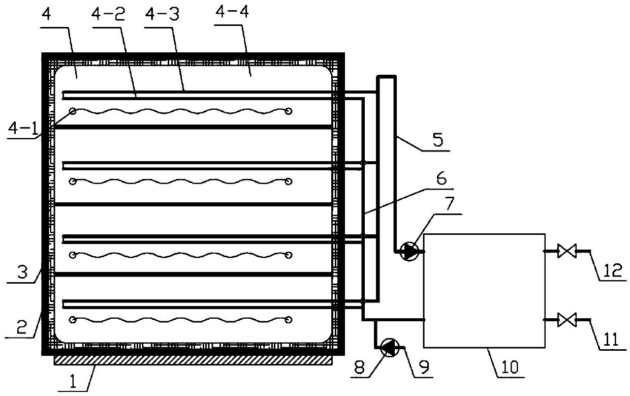
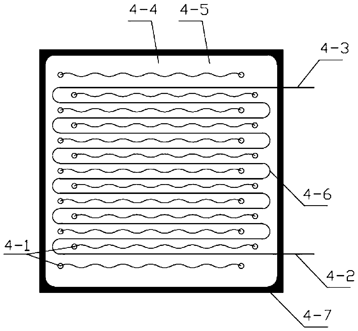
[0021] Such as Figure 1~2 As shown, the phase change heat storage device of the present invention includes a base 1 and a metal shell 2 fixed on the base 1. The inner side wall of the metal shell 2 is covered with an insulation layer 3, and several insulation layers 3 are arranged in parallel along the longitudinal direction. Phase change heat storage modules 4, each phase change heat storage module 4 is stacked up and down, the upper and lower surfaces of adjacent phase change heat storage modules 4 are attached to each other, and each phase change heat storage module 4 is placed directly or through a slot In the thermal insulation layer 3; the phase change heat storage module 4 includes a metal frame 4-7, a metal foam 4-5 evenly filled in the closed metal frame 4-7, and a phase change material 4 evenly filled in the metal foam 4-5 4.


PUM

PropertyMeasurementUnit
Apertureaaaaaaaaaa

Abstract

The invention discloses a phase change heat storage device. The phase change heat storage device comprises a metal shell. The inner side wall of the metal shell is covered with a heat insulating layer. A phase change heat storage module is arranged in the metal shell. The phase change heat storage module comprises a metal frame, foam metal arranged in the closed metal frame in a filling mode, anda phase change material arranged in the foam metal in a filling mode. A plurality of electric heating wires distributed evenly and a heat exchange coil arranged in a baffling mode are further arrangedin the metal shell, wherein the electric heating wires are connected with an external power source through an electric wire; a water inlet end of the heat exchange coil is connected with a water inlet branch pipe; and a water outlet end of the heat exchange coil is connected with a water outlet branch pipe. The phase change heat storage device has the functions of heating, heat storage and hot water supply, the principle of phase change heat storage is adopted, meanwhile, a heat transfer framework is formed through the foam metal, thus, the heat conductivity of the heat storage device is effectively improved, a heat storage box is arranged modularly, and manufacturing and maintaining of the device are facilitated.

Description


Claims


Application Information

Patent Timeline
Owner SOUTHEAST UNIV
Why Eureka
Try Eureka