Automatic corrugated pipe sensor of instrument

A bellows and sensor technology, applied in the field of sensors, can solve problems such as micro pressure cannot be measured, large leakage, easy freezing and blocking, etc., and achieve the effect of stable physical properties, small tension and strong stretching force

Inactive Publication Date: 2019-08-06
唐根林
View PDF5 Cites 0 Cited by
  • Summary
  • Abstract
  • Description
  • Claims
  • Application Information

AI Technical Summary

Benefits of technology

This new type of device called an electronic gauge can measure continuously producing machining tools at very extreme temperatures without damaging them permanently. Its main advantage over existing devices is its ability to work under harsh conditions such as heating up wells during manufacturing processes due to their thin design made from materials like ceramics or special alloys containing tantalum (Ta). These materials resist damage even when exposed to severe environments where they may be harmful if leaked into human bodies.

Problems solved by technology

Technological Problem addressed in this patents include issues such as difficulties in separating liquids containing harmful substances (such as hydrocarbons) due to their extreme solubility and susceptibility towards decomposition reactions caused by oxygen gas hydrates that can form solid deposits at various locations within equipment systems like automobiles, electronic devices, nuclear facilities, refineries, steel industries, and other industrial processes where sensitive materials may come into contact without being able to prevent damage or contamination. Additionally, current methods require multiple steps involving cleanup after each use, leading to waste and environmental concerns.

Method used


Image

  • Automatic corrugated pipe sensor of instrument
  • Automatic corrugated pipe sensor of instrument
  • Automatic corrugated pipe sensor of instrument

Examples


Embodiment Construction

[0020] The preferred embodiments of the present invention will be described in detail below in conjunction with the accompanying drawings, so that the advantages and features of the present invention can be more easily understood by those skilled in the art, so as to define the protection scope of the present invention more clearly.

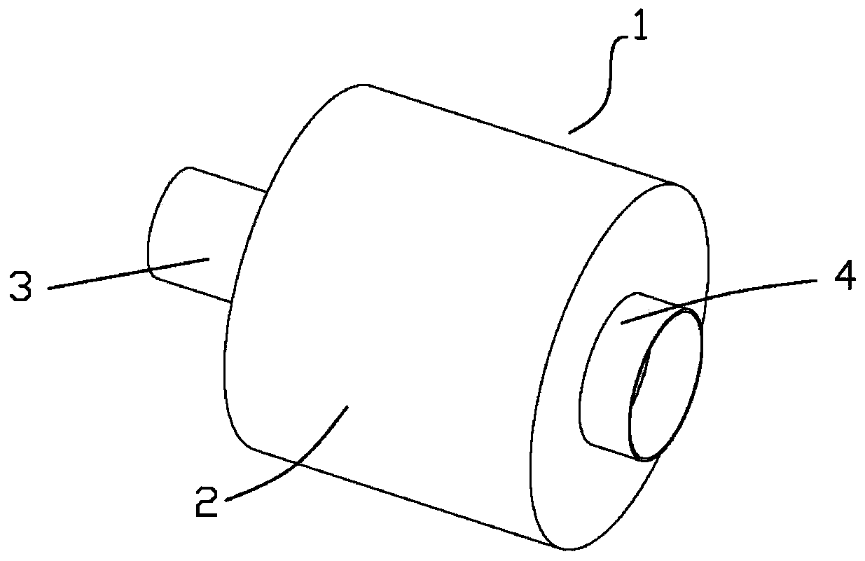
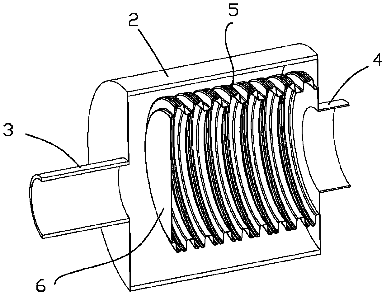
[0021] Such as figure 1 with figure 2 As shown, the instrument automation bellows sensor 1 includes a hollow cylindrical housing 2, the head of the housing 2 is provided with an inlet joint 3, and the tail of the housing 2 is provided with an outlet joint 4, the housing 2 is provided with a bellows 5, the head of the bellows 5 is provided with a sealing plate 6, the tail of the bellows 5 communicates with the outlet connection 4, and the bellows 5 is filled with silicone oil.

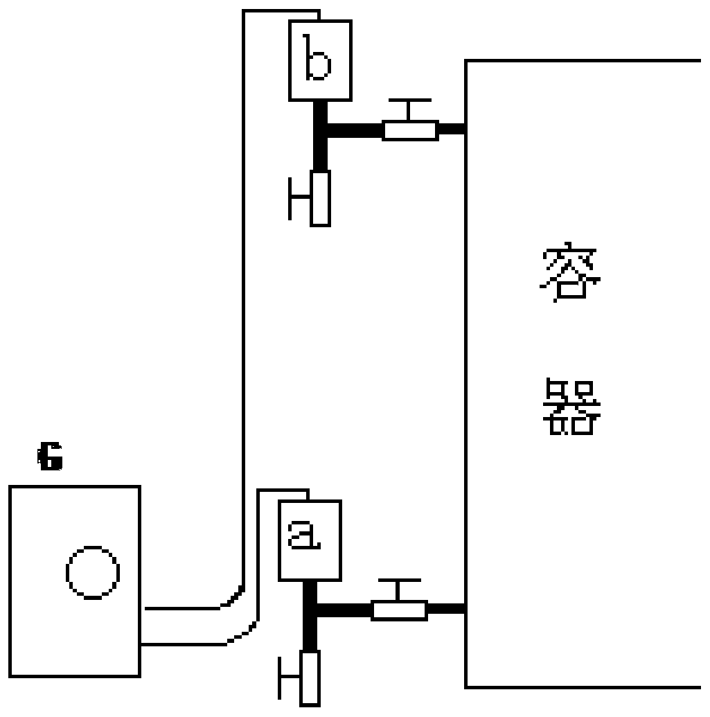
[0022] When in use, the inlet connection 3 is connected to the measured container or the measured pipeline, and the outlet connection 4 is connected to the transmitter or p


PUM


Abstract

The invention discloses an automatic corrugated pipe sensor of an instrument. The sensor comprises a hollow cylindrical housing. An inlet connecting pipe is arranged at the head of the housing; and anoutlet connecting pipe is arranged at the tail of the housing. A corrugated pipe is arranged inside the housing; a sealed plate surface is arranged at the head of the corrugated pipe; the tail of thecorrugated pipe is communicated with the outlet connecting pipe; and the corrugated pipe is filled with silicone oil. The housing and the corrugated pipe are made of corrosion-resistant resistant stainless steel or HC alloy materials. Because of various advantages of the sensor, technical problems of high temperature, high pressure, flammable and combustible properties for oil refining and chemical engineering in terms of instrument measurement of the continuous production device are solved. The principle of liquid incompressibility is employed; the ultra-thin corrugated pipe is only 0.12mm and is made of the corrosion-resistant stainless steel or HC alloy material; the superficial area of the large corrugated pipe with the large superficial area is ten times as large as the superficial area of the common transmitter film; the contractility is high and the strain is low; and the isolating liquid has the stable chemical and physical characteristics.

Description


Claims


Application Information

Patent Timeline
Owner 唐根林
Why Eureka
Try Eureka