Heat dissipation system for battery pack of new energy automobile

A new energy vehicle and heat dissipation system technology, applied in the field of new energy vehicle battery pack heat dissipation system, can solve the problems of reduced service life of power battery, poor heat dissipation effect, difficult disassembly, etc., and achieve the effect of improving heat dissipation efficiency and increasing service life

Active Publication Date: 2019-09-17
宁波里尔汽车技术有限公司
View PDF10 Cites 2 Cited by
  • Summary
  • Abstract
  • Description
  • Claims
  • Application Information

AI Technical Summary

Problems solved by technology

[0003] In the prior art, the heat dissipation effect of the new energy vehicle battery pack heat dissipation system is poor. When the external temperature is too high, the heat cannot be quickly removed, thereby reducing the service life of the power battery

Method used


Image

  • Heat dissipation system for battery pack of new energy automobile
  • Heat dissipation system for battery pack of new energy automobile
  • Heat dissipation system for battery pack of new energy automobile

Examples


Example Embodiment

[0021] In order to make the technical means, creative features, objectives and effects of the present invention easy to understand, the present invention will be further explained below in conjunction with specific embodiments.

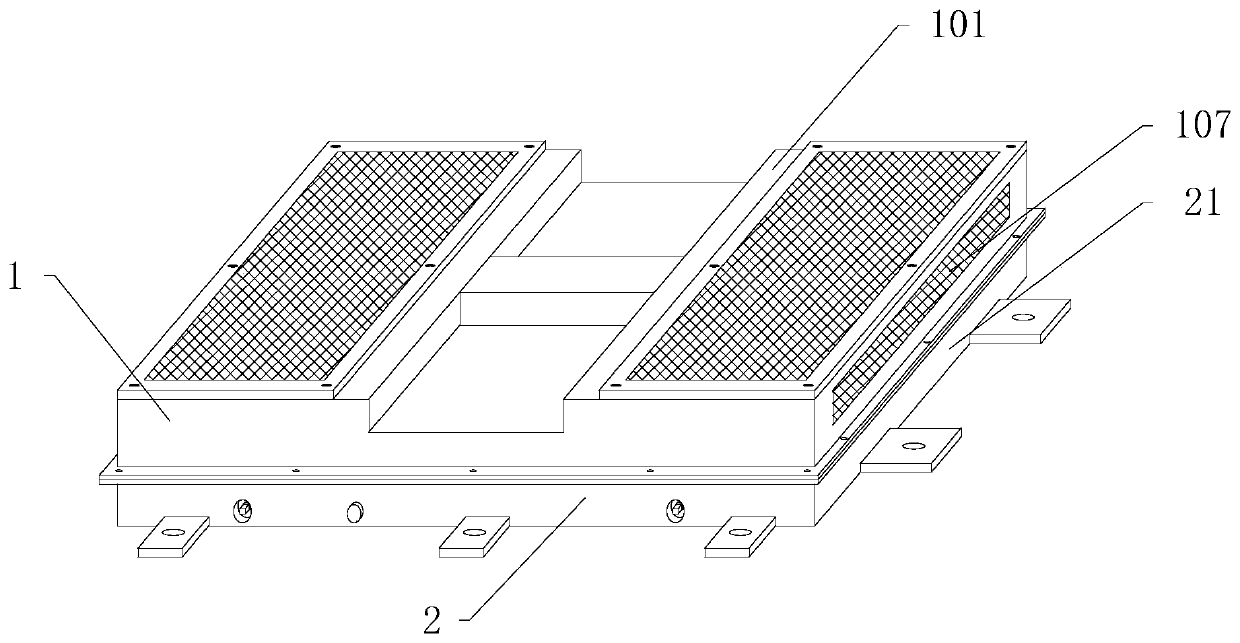
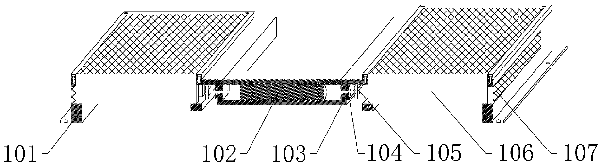
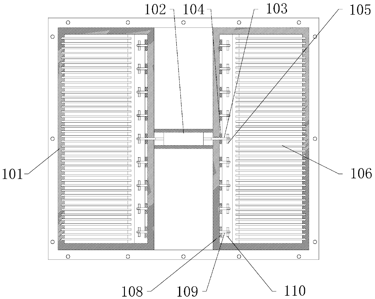
[0022] See Figure 1-Figure 6 , The present invention provides a technical solution: a new energy vehicle battery pack heat dissipation system, including a heat dissipation mechanism 1 and an auxiliary mechanism 2. The heat dissipation mechanism 1 has an auxiliary mechanism 2 installed at the lower end, and the heat dissipation mechanism 1 includes an upper shell 101, a double-head motor 102, The main shaft 103, the pulley one 104, the fan blade 105, the heat sink 106, the cooling net 107, the pulley two 108, the auxiliary shaft 109 and the fan blade two 110, the auxiliary mechanism 2 includes a lower shell 21, a bottom plate 22, a through groove 23, and a rotating shaft 24 and a curved single lever 25.

[0023] As an embodiment of the present invention: in


PUM


Abstract

The invention provides a heat dissipation system for a battery pack of a new energy automobile. The system comprises a heat dissipation mechanism and an auxiliary mechanism. The auxiliary mechanism is mounted at the lower end of the heat dissipation mechanism. The heat dissipation mechanism comprises an upper shell, a double-head motor, a main shaft, a belt wheel 1, a fan blade 1, cooling fins, a heat dissipation net, a belt wheel 2, an auxiliary shaft and a fan blade 2. The auxiliary mechanism comprises a lower shell, a bottom plate, a through groove, a rotating shaft and an arc-shaped single dialing rod. Compared with the prior art, the beneficial effects are that the fan blade 1 and the fan blade 2 rotate to generate air flows, and then the air flows blow the cooling fins, so the heat dissipation efficiency is improved, and the service life is prolonged; and by use of the arc-shaped single dialing rod, a person can conveniently take out the battery pack, and the operation difficulty is reduced.

Description


Claims


Application Information

Patent Timeline
Owner 宁波里尔汽车技术有限公司
Why Eureka
Try Eureka