Mobile terminal

A technology of mobile terminals and driving parts, which is applied to identification devices, instruments, telephone structures, etc., can solve the problem of losing the screen display function in the opening area, and achieve the effect of improving aesthetics

Pending Publication Date: 2019-09-17
BOE TECH GRP CO LTD +1
View PDF9 Cites 7 Cited by
  • Summary
  • Abstract
  • Description
  • Claims
  • Application Information

AI Technical Summary

Problems solved by technology

[0003] In order to solve the above technical problems, this paper provides a mobile termin

Method used


Image

  • Mobile terminal
  • Mobile terminal
  • Mobile terminal

Examples


Example Embodiment

[0024] In order to make the purpose, technical solutions and advantages of this document clearer, the embodiments of this document will be described in detail below with reference to the accompanying drawings. It should be noted that the embodiments in the application and the features in the embodiments can be combined with each other arbitrarily if there is no conflict.

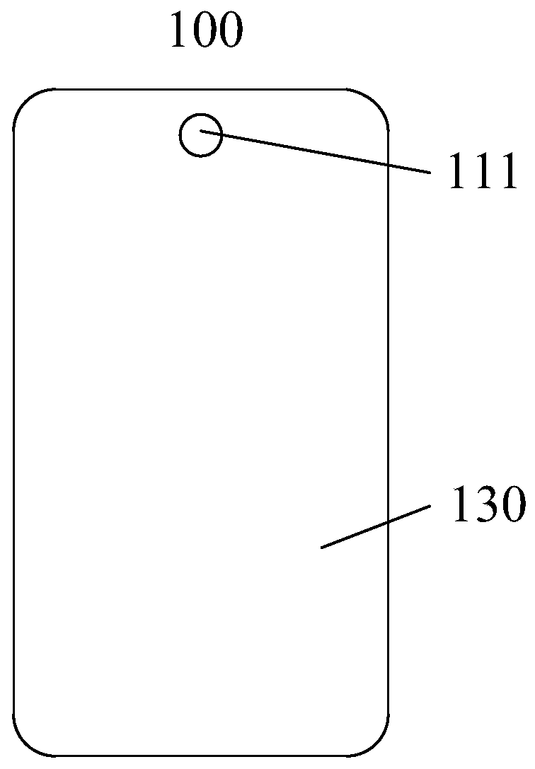
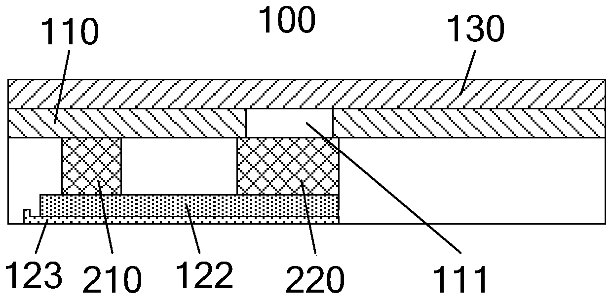
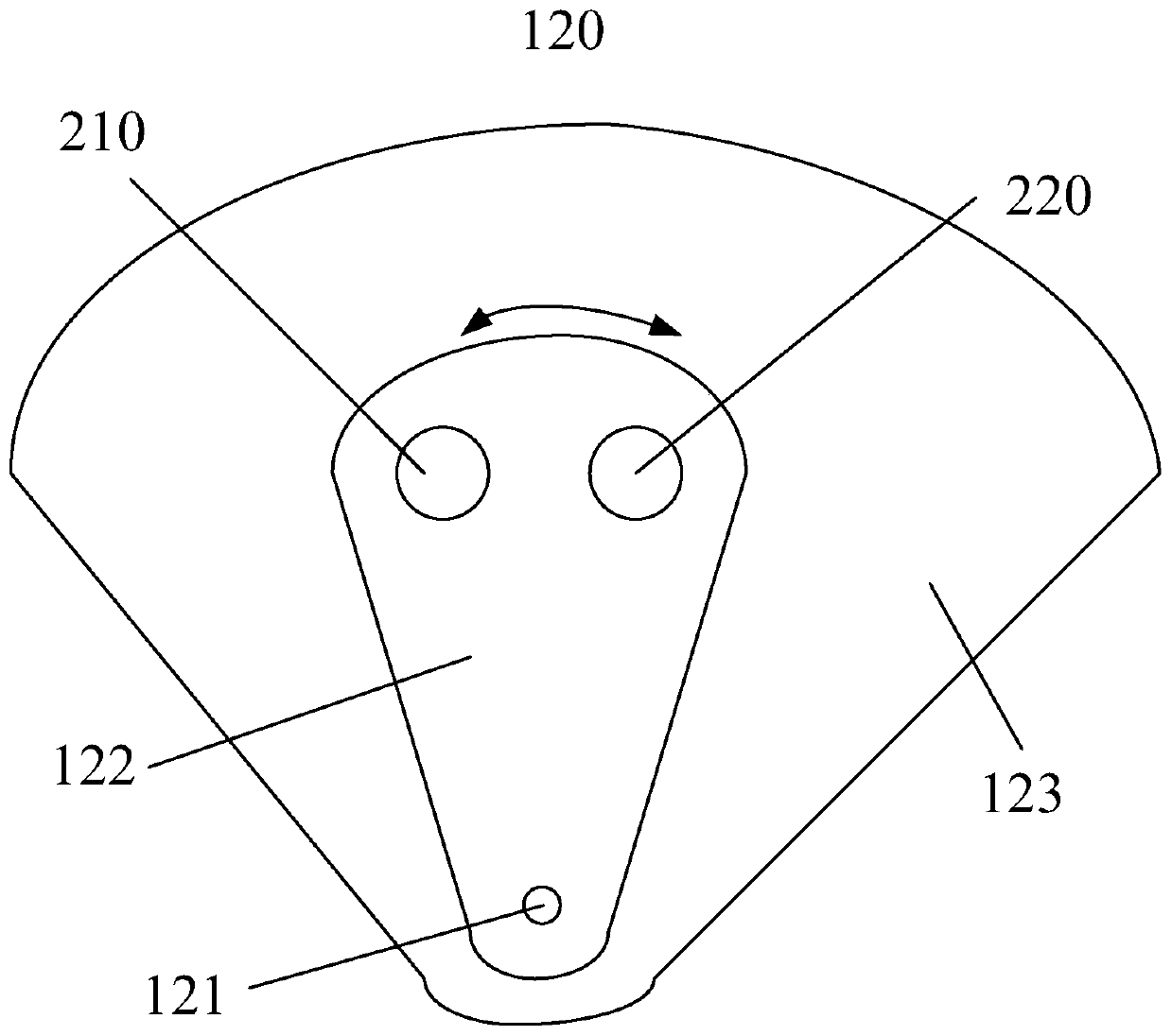
[0025] The mobile terminal provided by the embodiment of the present invention, such as Figure 1 to Figure 5 As shown, it includes: a terminal body 100 provided with a display panel 110, the display panel 110 is provided with a through function hole 111; and a switching mechanism 120, hidden and installed in the terminal body 100, the switching mechanism 120 is provided with a functional module 210 and The picture compensation module 220 and the switching mechanism 120 operate to realize that any one of the function module 210 and the picture compensation module 220 is switched to the function hole 111.

[0026] In


PUM

PropertyMeasurementUnit
Diameteraaaaaaaaaa
Thicknessaaaaaaaaaa

Abstract

The mobile terminal comprises a terminal body provided with a display panel, and the display panel is provided with a functional hole; a switching mechanism is installed in the terminal body in a hidden mode, a function module and a picture compensation module are arranged on the switching mechanism, and the switching mechanism acts to achieve switching of any one of the function module and the picture compensation module to the function hole. According to the mobile terminal, the switching mechanism is installed in the terminal body in a hidden mode, that is, the function module, the image compensation module and the switching mechanism are hidden in the terminal body and are not exposed, and the attractiveness of the mobile terminal can be improved; when the display panel performs display, the switching mechanism acts to switch the picture compensation module to the functional hole, and the picture compensation module displays the picture missing from the functional hole, so that the purpose of displaying the picture at the functional hole is achieved; when the functional module needs to be used, the switching mechanism acts to switch the functional module to the functional hole.

Description


Claims


Application Information

Patent Timeline
Owner BOE TECH GRP CO LTD
Why Eureka
Try Eureka