Clamping jaw structure for automobile engine cylinder body or cylinder cover

A technology for automobile engines and grippers, applied in metal processing, metal processing equipment, manufacturing tools, etc., can solve the problems of single grasping position, unstable grasping parts, etc., and achieve small size, high work efficiency and reasonable layout Effect

Inactive Publication Date: 2019-10-22
中国科学院沈阳计算技术研究所有限公司
View PDF13 Cites 1 Cited by
  • Summary
  • Abstract
  • Description
  • Claims
  • Application Information

AI Technical Summary

Benefits of technology

This technology combines movements for X-, Y-, and locked directions with an electric drive system called Cylinders (X) to achieve precise control over these motions without requiring complicated mechanisms like sprung bolts. It also allows for easy placement within limited spaces while maintaining its strengths against external forces such as impact force from collisions between vehicles during manufacturing operations. Overall, this innovative design improves safety, productivity, and quality by reducing complexity and size constraints on machinery used in car industry's engines.

Problems solved by technology

Technological Problem: Current designs have limitations when trying to use different types of tools together during certain stages of engine assembling process due to lacked space between them. Additionally, some parts may require extra support while other components work properly. Therefore, technical problem addressed by these inventions needs to improve upon previous methods such as fixed-jaw mechanisms.

Method used


Image

  • Clamping jaw structure for automobile engine cylinder body or cylinder cover
  • Clamping jaw structure for automobile engine cylinder body or cylinder cover
  • Clamping jaw structure for automobile engine cylinder body or cylinder cover

Examples


Embodiment Construction

[0023] The present invention will be described in further detail below in conjunction with the accompanying drawings.

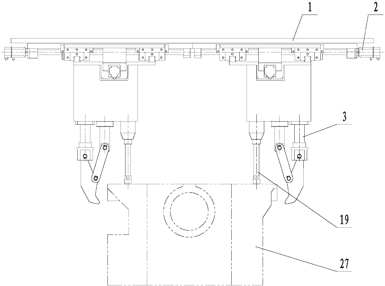
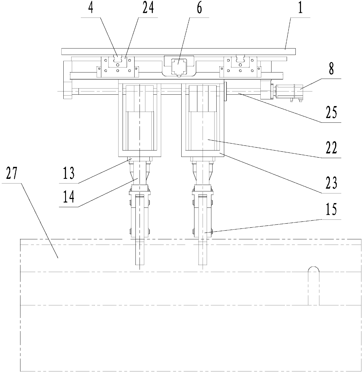
[0024] Such as Figure 1~5 As shown, the present invention includes a mounting plate 1, an X—Z sliding table 2 and at least one set of jaw devices 3, wherein the jaw device 3 is installed on the mounting plate 1 through the X—Z sliding table 2, and the jaw device 3 has the degree of freedom of reciprocating movement along the X-axis and Z-axis perpendicular to each other in the X-Z slide table 2. Two gripper devices 3 form a group. The gripper devices 3 in this implementation are divided into two groups and four. The gripper devices 3 on the same side in each group share one X—Z slide table 2 and are installed on the mounting plate 1. . A set of two gripper devices 3 are respectively located on both sides of the cylinder body or cylinder head, and the gripper devices 3 on each side are respectively installed on the mounting plate 1 through their own X—Z slidin


PUM


Abstract

The invention relates to a clamping jaw structure for an automobile engine cylinder body or cylinder cover. The clamping jaw structure for the automobile engine cylinder body or cylinder cover comprises a clamping jaw device, wherein the clamping jaw device is mounted on a mounting plate through an X-Z sliding table, the clamping jaw device has freedom degrees of reciprocating motion along the X axis and the Z axis which are perpendicular to each other in the X-Z sliding table, the clamping jaw device comprises a locking air cylinder, a linear shaft, a clamping jaw, a connection rod, a connection seat and a clamping jaw mounting seat, the clamping jaw mounting seat is connected with the X-Z sliding table, the locking air cylinder is arranged in the clamping jaw mounting seat, the linear shaft is connected with the clamping jaw mounting seat in a sliding mode, one end of the linear shaft is connected with a piston rod of the locking air cylinder, the clamping jaw is hinged with one endof the connection rod, the other end of the connection rod is hinged with the connection seat mounted on the clamping jaw mounting seat, one end of the clamping jaw is hinged with the other end of thelinear shaft, the other end of the clamping jaw is a clamping end for grasping the cylinder body or the cylinder cover, and the linear shaft, the clamping jaw, the connection rod and the connection seat form a four linkage mechanism driven by the locking air cylinder to stretch out and draw back so as to drive the clamping end of the clamping jaw to clamp or loosen. The clamping jaw structure forthe automobile engine cylinder body or cylinder cover improves reliability of the clamping jaw, and improves assembly efficiency on an automobile engine production line.

Description


Claims


Application Information

Patent Timeline
Owner 中国科学院沈阳计算技术研究所有限公司
Why Eureka
Try Eureka