PCB non-metallic material steel-plastic compound plate tray, preparing production line and preparing method

A non-metallic material, composite board technology, applied in sustainable manufacturing/processing, container, packaging recycling, etc., can solve the problems of high cost, low strength, poor impact resistance, etc. The effect of high bending resistance and high tensile strength

Inactive Publication Date: 2016-10-12
王传华
View PDF9 Cites 4 Cited by
  • Summary
  • Abstract
  • Description
  • Claims
  • Application Information

AI Technical Summary

Benefits of technology

This new type of platy materials called PCB (Print Circuit Boards) have several technical benefits that make them better than traditional metal or wood products. These improvements include increased mechanical properties such as flexibility, durability against environmental factors like humid environments, corrosion caused by saltwater spills, and longer lifespan compared with older alternatives made from metals. Additionally, they don't lose their effectiveness over time when exposed to harsh conditions during use because there won’s less chance of damage after multiple uses.

Problems solved by technology

Technological Problem addressed in this patents relates to improving the efficiency and reliability of producing lightweight loads while maintaining environmental sanitation during storage and shipage operations. Planning out these issues requires developing new ways to produce both strong and sturdy pallets without causing damage when handled manually or mechanically. Additionally, there may also require lower costs associated with manufacturing and maintenance compared to traditional ones.

Method used


Image

  • PCB non-metallic material steel-plastic compound plate tray, preparing production line and preparing method
  • PCB non-metallic material steel-plastic compound plate tray, preparing production line and preparing method
  • PCB non-metallic material steel-plastic compound plate tray, preparing production line and preparing method

Examples


Embodiment 1

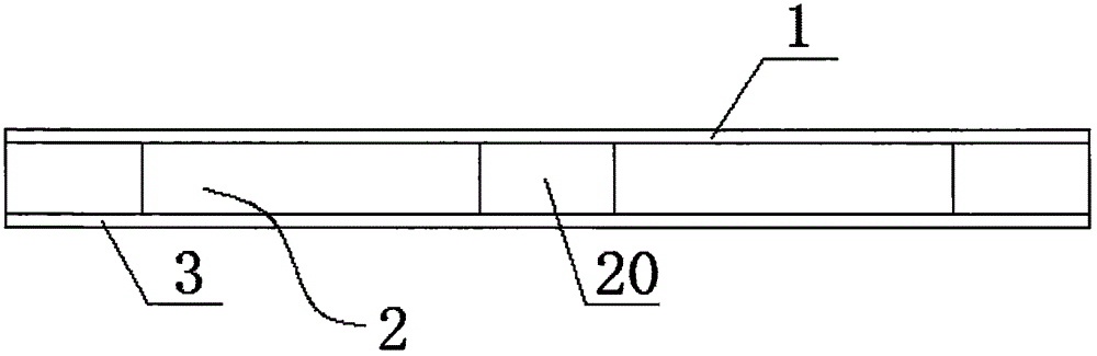
[0092] Such as figure 1 and figure 2 As shown, the PCB non-metal material steel-plastic composite board tray is characterized in that it is composed of a first steel-plastic composite board 1, a support layer 2 and a second steel-plastic composite board 3 arranged in sequence from top to bottom, and the support layer 2 is composed of several vertical columns 20, the first steel-plastic composite board 1 is fixedly connected to the top of the column 20, and the second steel-plastic composite board 3 is fixedly connected to the bottom end of the column 20, so Both the first steel-plastic composite board 1 and the second steel-plastic composite board 3 are composed of a first plastic layer 10, a reinforcement layer 11 and a second plastic layer 12 arranged in sequence from top to bottom.

[0093] Preferably, the column 20 is a solid cylinder made of polyvinyl chloride foam. The polyvinyl chloride uprights 20 can play the role of support and buffering, and on the other hand, it is

Embodiment 2

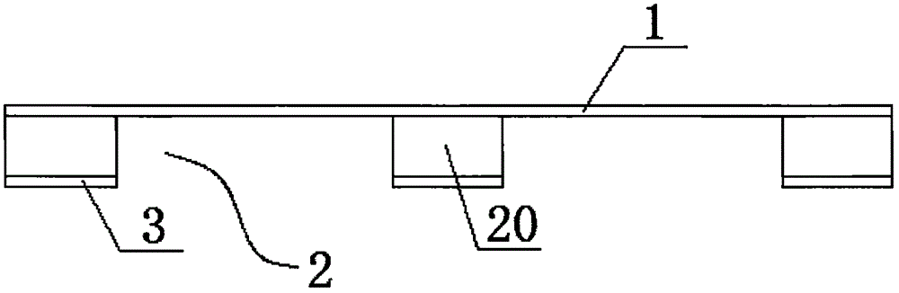
[0101] Such as image 3 and Figure 4 As shown, the PCB non-metal material steel-plastic composite board tray is characterized in that it is composed of a first steel-plastic composite board 1, a support layer 2 and a second steel-plastic composite board 3 arranged in sequence from top to bottom, and the support layer 2 is composed of several vertical columns 20, the first steel-plastic composite board 1 is fixedly connected to the top of the column 20, and the second steel-plastic composite board 3 is fixedly connected to the bottom end of the column 20, so Both the first steel-plastic composite board 1 and the second steel-plastic composite board 3 are composed of a first plastic layer 10, a reinforcement layer 11 and a second plastic layer 12 arranged in sequence from top to bottom.

[0102] Preferably, the column 20 is a solid cylinder made of polyvinyl chloride foam. The polyvinyl chloride uprights 20 can play a supporting and buffering role, and at the same time facilitat


PUM


Abstract

The invention relates to the field of logistics articles, in particular to a PCB non-metallic material steel-plastic compound plate tray, a preparing production line and a preparing method. The tray is formed by sequentially arranging a first steel-plastic compound plate, a supporting layer and a second steel-plastic compound plate from top to bottom; the supporting layer is composed of a plurality of vertically-arranged stand columns; the first steel-plastic compound plate is fixedly connected with the top ends of the stand columns; the second steel-plastic compound plate is fixedly connected with the bottom ends of the stand columns; and the first steel-plastic compound plate and the second steel-plastic compound plate are each formed by sequentially arranging a first plastic layer, a reinforcing layer and a second plastic layer from top to bottom. The produced tray can be recycled many times, resources are saved, the requirement of the 'green and environment-friendly industry' is met, the environment is protected, the tensile strength is high, the bending resistant performance is high, deformation is not likely to be caused, the deformation amount caused by the temperature effect is small, the shrinkage rate of thermal expansion and cold shrinkage is low, the number of using and circulating times is large, waterproofness is good, fumigation is not needed, and the service life is long.

Description


Claims


Application Information

Patent Timeline
Owner 王传华
Why Eureka
Try Eureka