Spraying system for mold cooling

A spray system and mold technology, applied in the field of mold cooling auxiliary equipment, can solve problems such as equipment aging, working environment pollution, etc., and achieve the effects of reducing energy consumption and water consumption, speeding up cooling speed, and facilitating recycling.

Active Publication Date: 2019-11-29
宁波宗炫机器人有限公司
View PDF8 Cites 1 Cited by
  • Summary
  • Abstract
  • Description
  • Claims
  • Application Information

AI Technical Summary

Benefits of technology

This patented technology allows for efficient use of liquid mist by rotating an endless robotic mechanism with different degrees of rotation. It also includes various features like adjustability of air pressure, fluid level detection, and temperature sensors. These improvements help improve efficiency and effectiveness while reducing costs associated therewith.

Problems solved by technology

This patented technical problem addressed by this patents relates to improving the efficient use of space inside dies castings during manufacturing processes without causing environmental issues or increasing wear on machinery due to overwatered coolant systems that produce waste products from excessive amounts of water being introduced into them through their pipes.

Method used


Image

  • Spraying system for mold cooling
  • Spraying system for mold cooling
  • Spraying system for mold cooling

Examples


Embodiment Construction

[0029] Below in conjunction with specific embodiment, further illustrate the present invention. It should be understood that these examples are only used to illustrate the present invention and are not intended to limit the scope of the present invention. In addition, it should be understood that after reading the teachings of the present invention, those skilled in the art can make various changes or modifications to the present invention, and these equivalent forms also fall within the scope defined by the appended claims of the present application.

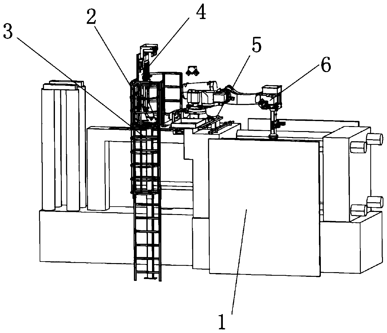
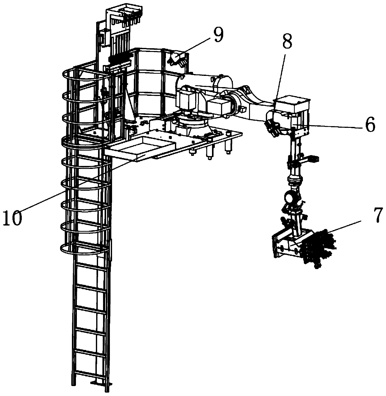
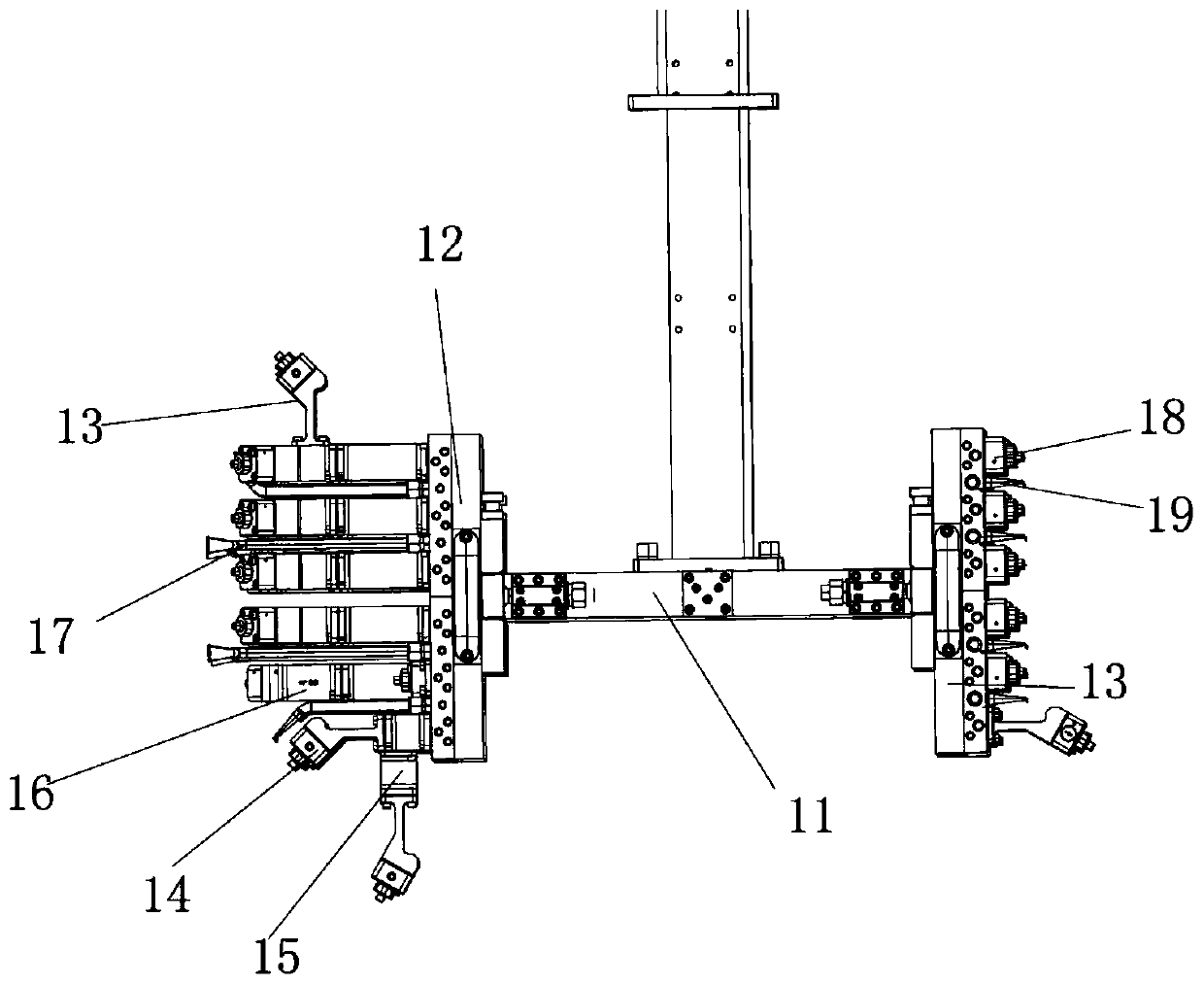
[0030] Embodiments of the present invention relate to a spray system for mold cooling, such as figure 1 - As shown in 11, it includes a manipulator installation platform 5, a machine platform 2 and a manipulator 6. The machine platform 2 is installed on the upper end surface of the die-casting mold machine platform 1, and the machine platform 2 is equipped with a manipulator near the mold clamping position. Mounting platform 5, m


PUM


Abstract

The invention relates to a spraying system for mold cooling. The spraying system comprises a manipulator mounting table, a machine table and a manipulator, wherein the machine table is mounted on theupper end surface of a die-casting machine table; the manipulator mounting table is arranged at the position, close to a mold closing part, of the machine table; the manipulator is mounted on the manipulator mounting table, wherein the end of the manipulator extends into the mold closing part; a valve box assembly is vertically mounted on the machine table; the manipulator is multi-section rotating shaft type; and a spraying assembly is mounted at the lower end of the manipulator. The spraying system for mold cooling has the characteristics that the installation is convenient, the operation issimple, the energy consumption and the water resource are saved, the work environment is ensured to be clean, the cooling speed is improved, and the like.

Description


Claims


Application Information

Patent Timeline
Owner 宁波宗炫机器人有限公司
Why Eureka
Try Eureka